NeilP
1 GW
I wonder if any one could take a look at the attached schematic for me.
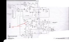
It is a PSU board on a David Clarke aviation noise cancelling headset. Original schematic DC themselves sent to me many months back.
It is designed to run from either a 6volt battery supply, or external power 10-32 volts.
The original plastic battery case has now become brittle and is scrap. so i could just re build in another case and continue with the 4 xAA pack..but I already have other kit that runs from 9V PP3 so to run this from 9v would be more convenient
The board is designed to take either 6 volt from the internal pack or 10-32v from external aircraft source, and feed 12 volt out to the headset NAR units.
U2 the MAX761CPA produces the 12 volt out, and can take up to a 16.5 volt input. So as far as that goes 9 volt is no issue
The alternative supply from the aircraft panel supply is via U1 LT1176CN8 This accepts from 10-32 volts.
U1 outputs 6 volt to feed U2, which then converts back up to 12volt which is fed to the headset ANR unit.
I have tried 9 volt in at the 10-32 volt input and this is a little too low to be stable, and drops out.
Since U2 can take up to 16.5 volt in, then I suspect that sticking in 9v where it expects 6v would be OK.
Except for the one issue that I can see, that this question is about.
I think I know the answer, but no being an EE I want someone that actually knows about these things to look first and see if I have missed anything that would cause me to damage the unit. Replacement is $220 USD!!)
The resistive divider network R4 and R5, drops the 6 volt input down to 2.3 volts, to feed the battery status indicator LED, via the Op-amp U3.
Obviously if I stick in 9volts, that is going to put this R4 - R5 junction to 3.5 volts or so..higher than the spec printed on the schematic..of 1.5 to 3 volts.
So my guess is that if I change R4 to 150kΩ and R5 to 51kΩ ( or swap out R4/R5 with a 200k pot), that is the only change I need to make the battery feed circuit work at 9 volt and keep the battery indication working correctly.
Have I missed anything?