2WD Electric scooter

scootye

10 µW
Joined
Sep 17, 2019
Messages
6
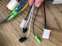
I am trying to setup my electric scooter with two hub motors, two controllers, one throttle and one battery pack. The throttle is a twist one with just battery indication. The motors are the same 36V motors and the controllers are both 36V as well. The throttle connects to one controller in the picture, with red white and black going to a three prong connector. Then the yellow and green from the throttle go to the another red from the controller and the brown from the throttle goes to the Orange of the controller. For the second controller. There is a three prong port for the throttle which is red black and green. There is also a brown wire, two white ones, and a purple one. I connected them both the the battery and they both receive 36V. Then I connected the white throttle wire (signal) to the original controller and then forked it to the other controller, but did not connected the throttle to the black and red of the other controller because it doesn’t need two power sources. When I twist the throttle, the one motor runs on the original controller, but the secondary controller that is only getting the throttle signal doesnt do anything and the motor doesn’t spin. I measured the voltage on the signal from the throttle and both controllers get around 1-3v depending on throttle rotation. Why is the second controller not responding to the throttle. Are there more connections I have to make between the two? Please help View attachment 2View attachment 16DFE931D-04BF-4A35-AF21-59A9AF2DAD5E.jpeg
 
Hi scootye,

From your description it sounds like you armed the first or "main or master" controller's ignition or key lock circuit. (controller's Red to throttle's Yellow wire, thru the key switch, back down on the brown, to the controller's orange wire. Does the second or "slave" controller also have a ignition circuit that needs to be energized for operation?

Keep all brake connections disconnected while troubleshooting.

Controller information would be helpful. (links, wiring diagrams)


Regards,
T.C.
 
This is the link for the slave controller, US $5.61 37% Off | 36V/48V 350W Electric Bicycle E-bike Scooter Brushless DC Motor Controller Drop Ship Support
https://s.click.aliexpress.com/e/tIBVzBYc

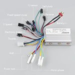
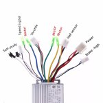
It doesn’t have labels but I found the picture below from another very similar controller.

This is the link for the master controller and throttle, US $76.99 30% Off | Electric Bike Conversion Kit 350W 24/36V/48V Brushless Hub Motor Kit With Front Wheel 8inch Brake Controller LCD Throttle Handle
https://s.click.aliexpress.com/e/LQf3p464

And I put the wiring diagram for it below as well.

I’m not sure if there is a power lock for the slave controller1E1E5630-7010-4993-B794-9E59ACFF80ED.jpeg02882E81-A697-4808-891D-4B7A4BEE92BD.jpeg.
 
Using your pictures for reference...
I see the master controller on the top picture, and the slave underneath it. It appears that the slave controller does indeed have a power lock circuit. You see the small Red wire included in the Power connector? This one needs to have full battery positive power switched to it, just like the single orange wire in the master controller.

Since these circuits use so little current, often around 40 mA each. And using one battery for both. I see no reason why you couldn't tie the throttle's switched power wire (Brown) to both controllers Power Lock circuits. (Orange wire on the master and small Red wire on the slave) This will energize both controllers with the turn of a key.

But I would recommend taking a step back, and separating both of these systems. Until you have run both controller's learning functions and have them locked in for their respective motor's phase to hall sensor configuration. And tested operation with throttle on both to make sure everything is working correctly...(unless you have done this already...) :wink:
 
What I already did was have a wire going from the thick red wire on the slave to the thinner power lock red wire of the slave like you stated, so it is already directly powered by the battery. If you think it makes more sense, I can connect it to the brown throttle line instead of the battery if that might help it. In the long run, I’m going to have the slave be controlled by a second switch on top of the throttle key but that’s irrelevant for now as I test everything. For your last point, I will test the slave with the one motor by itself as I haven’t check that one. Let’s see what happens. Thanks for the suggestions
 
First off, thank you very much for the links and posted snapshots. It is well worth the time to be on the same page of understanding. And it gives one a glimpse of other interesting products that are out there! Had a double take on the less than 6 dollar controller.. wow. :eek:

If your planning on not running both controllers at the same time, then no you wouldn't want to tie the power lock wires together.
If you are going to switch everything on/off at the same time, then yes I would think tying them together would be a very elegant and practical way to do it. Along this line you may want to switch the LED green power wire over to the brown wire also, so the charge display also comes on with the key. I would verify the total amperage draw of these three circuits together to make sure your key switch can handle it.

But as you say, the power lock was not the problem. :?

The only other thing that stands out is the low voltage output reading of your throttle. 3vdc at WOT would indicate that the input voltage would probably be below 4vdc. This is unusually low and may indicate an higher than normal power drain some where...?
Perhaps the slave controller's 5vdc regulated power supply would be more up to the task? Something to check...
 
So a few things, this time I connected the throttle to the slave only with the power lock and everything and the motor didn’t turn, seems like a busted controller. Luckily I had another, so I did everything together, put the power lock to master and slave, put the signal of master to slave, and power slave directly to battery, and both of them turned on together!! Not sure why the other one was busted, might ask for a replacement. Now, I am just going to add a switch for the slave on its power line so that both the throttle key have to be turned and the switch has to be turned on for the second motor to run. One thing I notice is that even when the throttle is plugged in but the key is not turned or I even remove the key, the lcd is still on, so I might add a switch to break all circuits starting from the battery because the lcd would just drain it when my scooter is idle. Here comes a lot of soldering! Thanks for all the help as well
 
Job well done on solving the problem!

Did you try the learning wires on the probable busted controller?

scootye said:
One thing I notice is that even when the throttle is plugged in but the key is not turned or I even remove the key, the lcd is still on, so I might add a switch to break all circuits starting from the battery because the lcd would just drain it when my scooter is idle. Here comes a lot of soldering! Thanks for all the help as well


TommyCat said:
Along this line you may want to switch the LED green power wire over to the brown wire also, so the charge display also comes on with the key.

To be clear... my suggestion above would result in the display being turned off when the key switch is turned off. :thumb:
Move the throttle Green wire from the throttle Yellow wire, to the throttle Brown wire. (from the battery power + that's on when the battery is plugged in, to the "switched" side of the key switch that is only powered when the key switch is turned ON.

Glad to help! :D
 
Back
Top