Fuse-wire for individual cells, DIY Tesla style

Another informative video on the future of Tesla batteries beginning with the Tesla Y and going forward with a new dry battery chemistry that looks to distance Tesla's need for Panasonic. Will Elon Musk eventually overtake all the other major auto companies with the best competitively priced electric car ??? ...

[youtube]hjCnuyqEacQ[/youtube]

Assuming Tesla Style fuse~wiring remains an integral part of their new batteries is it because its always been more about less cost and reduced production time than safety ???
 
fechter said:
Yes, excellent, thanks! I've seen friction welding of high tech plastics but not yet metal.

Odds are slim of any DIYer getting the same results.

I doubt if this methodology is in any way a compromise, very likely optimal for all three factors mentioned.

Tesla has a lot at stake, being the most valuable U.S. auto maker ever.

> The company closed Monday with a market value of $81.39 billion, surpassing Ford Motor Co. 's peak of $80.81 billion set in 1999.

 
Tesla is now valued (insanely) higher than GM and Ford, **combined** !

What a world we live in.

SHTF one day for sure
 
spinningmagnets said:
Some builders are interested in individual cell fusing, and some are not. To each their own. I only started this thread so any accumulated info about this will be all in one place.

If you are arguing against cell-fusing, then dont cell-fuse when you build a pack.
Certainly NOT opposed to cell~fusing for DIY ebike performance packs, even moreso when not including a SMART BMS that will also balance the cells during the entire charging process as the pack ages.
spinningmagnets said:
Fuses cost more, and the majority of customers are extremely price-sensitive.
John in CR said:
I don't think our ebikes have a large enough parallel structure for individual cell fuses to provide an overall safety benefit, because they would make killing an entire parallel group more likely.
spinningmagnets said:
That's a good point, I agree.
[youtube]tetR1QHzHrM[/youtube]

Tesla's Total Battery SAFETY innovations (raw performance and longevity), including VERY SMART Battery Maintenance Systems were suspose to prevent a battery fire. After two Tesla's hit debris in the road, piercing the car's underbody and a Federal Safety investigation all Teslas now in production have a triple underbody shield. That includes a hollow aluminum bar, a titanium plate, and a solid aluminum extrusion. Even after the fires, Consumer Reports picked the Tesla Model S as the best car overall car in 2014.

Tesla's latest battery uses different lithium cells (21700), and its liquid battery cooling system differs significantly from the Model S and X cooling design. ... https://www.latimes.com/business/story/2019-11-01/federal-safety-agency-launches-investigation-of-tesla-battery-fires ... It's rumored that Tesla has also obtaned 21700 cells from Samsung as Panasonic Gigafactory isn't yet able to keep up with production demands. It's also rumored that they are high capacity Samsung cells. Currently Li-NiMnCoO2 (LNM 8-1-1) seems to be the industry preference for all around cost and performance.
 
Yes aka lithium nickel manganese cobalt oxide or NMC, certainly more powerful than, adding nickel to the "old spinel IMR" aka LMO.

I believe also used in:
Sony / Murata VTC6
LG INR18650M36T aka M36
 
For DIY spot welded packs, welding a fuse wire to a cell seems problematic. So cost and effort probably outweighs the reward in that case.

For packs that are soldered, since it really only involves sizing the cell connecting wire appropriately and soldering those wires to a larger common "bus" wire, cell level fusing seems more practical.

It still probably won't protect against full pack thermal runaway if one cell actually burns, since the majority of ebike packs don't have adequate cell-cell thermal protection to stop a chain reaction.

But, possibly it will remove a cell that is starting to go bad, and reduce the chance that it will continue to be (over)loaded until catastrophic failure.

As a rough example: Say you run a pack with cells in 5P, and say you want to pull up to 10A per cell, so each cell is fused at 20A, and these cells have an internal resistance of 20mOhm. In this scenario, say one cell starts to sag more under load due to increasing internal failure. Each cell needs to supply 20A/4=5A each back into the bad cell to blow the fuse. The voltage difference only needs to be about 20mOhms*5A = 100mV to the bad cell. This is rough figures, but gives an order-of-magnitude to work with.

It might add some value to do cell level fusing if you're soldering your packs. The possible downside will be for those pulling high amps, that are concerned about voltage drop through the thin fuse wires. That should be considered too.
 
Hi,

I'm thinking about building my first Li-ion 10S6P battery pack for an ebike and have read this thread on individual cell fuse wire with great attention. What I retain from the 8 pages of this thread is that, generally, fusing individual cells seems like a good idea or a nice to have feature on the paper. However there are also some disadvantages. I list 4 of them that come to my mind at the moment based on what I read in this thread:

a) Fuse wires are tiny and subject to mechanical/thermal stress (unless they are positioned to allow for some flex). This added complexity could make the pack unreliable.

b) Fuse wires must be appropriately dimensioned in order to break when needed yet not create too much resistance under normal loads (voltage sag)

c) Fuse wire must be soldered onto the cells, which may heat damage them.

d) Cell level fuse is not really necessary on an ebike pack size because the size of parallel groups is limited and the current flowing for other cells to one dead cell may be not enough to burn up the fuse unless it is made so tiny that it would create massive voltage sag under normal circumstances.

I do not want to start this discussion all over again but here is why I may consider cell fuse wire for my application. I don't own a spot welder and don't want to invest in it. I don't want to directly solder onto the cells and risk heat damaging them (please read further...). I also don't really like things like the Vruzend kit etc. I much prefer BatteryBlocs from Shawn McCarthy but still question resistance especially since current needs to flow through the magnets and a steel plate (although he demonstrated that this is not an issue in terms of temperature). Beside going with the N.E.S.E module route, this leaves me with two options:

1) Use copper foil as bus bars and use magnet to hold the copper foil on the cells
2) Use 18650 cells with U soldering tags, bend the tags and solder a fuse wire onto a copper bus bar

I feel like option 2) would be easier to achieve. First soldering a small wire on a soldering tabs isn't going to heat the cell and should be achieved pretty quickly. So it is both easy and safe for the cells. Second, having fuse wires add some peace of mind to the build although it may not be needed after all. Finally, this saves the weight of magnets which would add approx 300g to the battery (not a real issue for me but still good to have a lighter build). So I'm actually heading towards using fuse wires not primarily for the added safety they're suppose to provide but really because in the builds I'm considering, it looks to me that it would be easier to use them with 18650 batteries having U-tags without risking to damage the cells (actually even less than directly soldering the tags to a bus bar actually).

Now what I really wants to avoid is creating voltage sag by using those fuse wires. Basically I like the added safety marging those fuse provide (if they really do in an ebike pack) but I don't want to have voltage sag. I intend to draw max 20A from the pack which means 3.4A per cell in a 6P design. I would likely be using Samsung 29E cells (with U tags) which can output max 8.25A. Initially I though about using 5A fuse wires so that it may burn around 8-10A I guess. But this would likely end up with a massive voltage drop which is unacceptable. Do you think that it would be appropriate to use a 10A rated fuse wire in this setup (even if the fuse blows at e.g. 15A) without create significant voltage sag? I understand that this may not be the safest option and one may like to have the fuse blow earlier. But remember we're comparing a build with and without fuse wires. So having fuse wires (even if they are a bit oversized) will still be safer than not having any fuse wires at all. And a slightly oversized fuse wire should be strong enough to handle mechanical stress (I'd slightly bend them to accommodate some movement due to heat expansion). In any case, I will use a pack level fuse rated at 25-30A anyway + a smart BMS with bluetooth communication to monitor cell voltages.

Would be glad to know your opinion about this and whether there is some sense in what I intend to do or not at all, and especially whether using 10A fuse wires would be appropriate here without creating voltage sag. I'd be using copper bus bars for series connection so may goal is to have a pack that has no more voltage sag than a pack that is spot-welded with 8mm wide and 0.2mm thick pure nickel strips. Since the copper bus bars will lower the resistance compared to nickle strips, this should leave some room to add some resistance in the fuse wires... Thanks!
 
I think you are pretty far along in your theoretical knowledge.

Good basis to support actually starting physical A/B testing.

Especially in including near-EoL cells mixed in with high capacity new ones, try to actually trigger some risky scenarios and see if this is a solution to any likely to be encountered real problems.
 
Well I'd certainly use brand new cells for this build anyway. I doubt having the skills to properly test different scenarios honestly since it would be my first build. I only found interesting that from my perspective, using fuse wires looks like to be a simpler and safer solution for the building process (I mean safer because it doesn't require to heat-up the cells so much since it's quick to solder a wire on a solder tag than soldering tags directly) and that the actual "benefits" of having the added safety feature of fuse wires is actually a welcome by-product but not the seeked primary goal since it is yet to be demonstrated whether fuse wires are actually working for ebike packs. The only thing I'd like to be able to test though is the voltage sag. Is there any way to predict the voltage sag that the pack would experience using e.g. 10A fuse wires for all cells (both negative and positive terminals) + thick copper bus bars (1mm, 8-10mm wide) for series connection versus the same pack built with 0.2mm thick 8mm wide pure nickel strips for all parallel/serial connections?
 
only through measuring actual resistance of the completed assembly

for any level of accuracy
 
kilou said:
and especially whether using 10A fuse wires would be appropriate here without creating voltage sag. voltage sag than a pack that is spot-welded with 8mm wide and 0.2mm thick pure nickel strips.
FWIW, (JMO) fuse wires are more suited for Power Walls (e.g. using reclaimed cells). Don't need to tell you that a SMART BMS is essential for your DIY build :thumb:

Should hear back in a few days from a knowledgeable insider if the HD LiveWire with Samsung cells (equiv of 105 hp, 0 to 60 in 3 sec) uses fuse wires ... as well as his take on the use of 10a fuse wiring as extra protection with a SMART BMS for your ebike application.
 
Hello guys, I'm planning to use this technique on my massive 14S8P 21700 P42A pack, but I'm not sure what kind of fuse I should use. I want the fuse to blow up, when exciding 45A, since that's the maximum the cells can handle.

I designed my pack to be fully welded on the negative and fused on the positive side. What conductor would you recommend? Fuse wire or small nickel strips? Does this introduce voltage sag?

The main plates are going to be lasercut out of copper and welded using the sandwich technique with nickel:

 
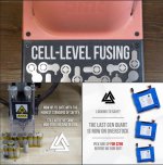
Thoughts on this? Seems more like marketing to me than actual functional advantage. I would think it's still going to require a lot of heat to melt the fuses.

CellFuse.JPG
 
I though the fusible wire got soldered onto the positive end?

I was looking at just a magnet for the negatives
 
I like using magnets over copper-foil on the negative end for a "cold connection", but some people don't like that (I don't know why).

The positive end is very robust, and I think even soldering nickel ribbon or copper ribbon would not hurt the positive (with proper tools and methods).

I've been told that an IR camera can show the heat gradient when a cell is warming up, and the positive end runs a little warmer than the negative end, and it's been speculated that its because the positive end draws its current from the center of the cell,with the outer wrappings of the roll insulating the inner wrappings.

The active material starts out as a series of stacked sheets, and is rolled into a cylindrical shape. The negative end is drawn from the outer skin of last wrap of the jelly roll. I'm not saying the bottom and sides are "good at shedding heat", I'm saying that the positive end has all of it's heat held in.

The positive end is the best place for a fuse-wire if you are adding them. That being said, they would still work on the negative end.

My statement about the low joules of the spot-welding a fuse-wire is about the fact that many builders still use 100J to spot-weld nickel ribbon onto the negative end. That's a LOT of heat. At 4 Joules for a fuse wire, I think you could touch it with your bare hand immediately after a weld.

This video of welding fuse-wire is for a large pack in a home-power-backup. They draw very low amps per cell under all conditions. Ebikes tend to draw high amps, so if fusing, it would take a fatter fuse-wire, but I suspect that it would still be using very low welding current.
 
Back
Top