Open Source Battery Equalizer

fechter

Administrator
Staff member
Joined
Dec 31, 2006
Messages
16,545
Location
California Bay Area, USA
I decided to start a new thread since the original thread was getting pretty long.

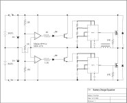
Here's a schematic I drew up about a year ago for a battery equalizer. This one is designed for a pair of 12v lead batteries. For higher voltages, you gang them like a PowerCheq. The same basic design could be adapted for equalizing Lithum batteries.

This design is theoretical and has not been built or tested. It might not work at all or need some tweaking.

The circulating diodes across the FETs are unnecessary if your FETs have the diodes built in.

This was intended to be sort of a minimum cost circuit, with minimum parts. More features could be added with more complexity. A PIC microprocessor could replace part of the circuit.

An ideal battery equalizer should have the following properties:

-Maintain equal voltage on the cells within a specified tolerance (.05v?)
-Be able to shuttle large currents to maintain equality. At least 2A.
-Operate over a wide voltage range or have a selectable voltage.
-Draw practically zero current when the cells are equal.
-Have some visual indicator of when it is working (or not working).
-Have some indicator of when a cell is weak that points to the weak cell.
-Be fault tolerant and protected against misconnection.
-Contain a minimum of parts or use the cheapest set of parts that would work.
-Compact size
-Minimal heat dissipation
-water resistant
-Dream on...
 

Attachments

  • PowerCheq Clone.jpg
    PowerCheq Clone.jpg
    24.9 KB · Views: 7,639
Seems to me that what you want is to be able to wire your batteries so that they have the charge protection and undervolt protection all the time like those Lithium cells with built in PCB's. If you could wire your entire battery pack so that the voltage restrictions were attached to tha battery and there was an LED light that was either "Red" (done) or "Green" (charging) then you could simply watch the process as it happened. If one cell was always "misbehaving" then you would be able to see it really quick. The charger then becomes little more than a source of current and the control logic goes all the way down to the battery itself. (when charging is complete you have a "christmas tree" display) Basically the charger should be "built in".
 
In programming theory this was called "Object Oriented Programming". This means that if you "solve" the problem at the smallest level then on the larger "macro level" you don't have to think about it at all. The alternative (older) approach was to look from the "Top Down" onto a problem and try to solve it using a centralized mindset. The more "distributed" the control logic the easier things tend to resolve themselves.

So I'd say "GO OOP"! :lol:
 
great idea Fetcher,maybe someone could open up their powercheq see how they do it.

I don't think it would be such a good idea for lithium better to just have cutoffs rather than balancing. If the pack keeps cutting off too soon then you know you have a bad cell to replace. That way the bms forces you not to run knackered cells and keep a healthy pack.
 
I'd like to see a PowerCheq. I have no idea how they do it. Just a pic of the insides of one would be interesting.

I'm not so sure about not wanting equalization on a lithium pack. It might help the cells from going bad in the first place. It certainly does this on a lead-acid pack.

Even if it didn't, it would extend the useful life of a pack.
Just for example, if you had 10 cells of Li and one cell was at 50% capacity compared to the rest. If you just monitor, then you could only get 50% of the capacity from the whole pack. If you balance (and mointor), you could possibly get over 90% from the same pack because the stronger cells will transfer charge to the weaker one. If you build a pack with cells from the same batch, they will tend to all crap out around the same time. Changing one cell on a 5 year old pack will probably be a waste of money.

If the balancer worked well enough, it might be unnecessary to monitor individual cells. It would make charging with a single charger much simpler. You could use a single high and low voltage monitor to protect the pack. This would basically eliminate the need for a separate BMS.
 
:arrow: Fechter...

I'm not sure I got my idea across... or you didn't register it...

If you focused your design around an "OOP concept" or simply focused on each individual cell then you could build something simple ONCE and then reproduce that same simple idea over and over and over.

Basically I'm asking you do design a "simple circuit" that protects just one cell at a time LIKE A PCB DOES, but it would be something that you could create in your garage with a soldering iron.

If you could incorporate the "Red" and "Green" LED's into the design to demonstrate a "charged" cell then you have "built in" to your battery pack it's own charging "awareness" and protection mechanism.


:arrow: Here's the specification for the circuit:

Circuit applies to ONLY one cell. (no outside wires allowed)

Input - Positive lead

Output - Negative lead

Limits upper and lower voltage for charging and discharging.

When charging is complete the "Red" LED is on.

When charging is not complete the "Green" LED is on.

When not charging no lights are on.

When draining the battery no lights are on.


(note: obviously the only time the lights are on is when the voltage is higher than the battery voltage... when the battery drains then no losses are expended on lighting up the LED's)
 
In order to have balancing, you need at least two cells. A module could go between two cells to balance them. You gang them together for more than two cells, like a PowerCheq. No limit to the number of cells. Voltage monitoring could be done on each cell, like you show, but you need to communicate that to the charger or controller to cut off when you reach the limit. Since each module would be at a different voltage in the string, you might need an optical isolator or at least some transistors that can take the full pack voltage.
 
:arrow: What's to balance?

If each cell can either:

1. Decide to accept the charge and absorb energy.

2. Decide to reject the charge and pass the energy along while alerting the status with a "Red" light.

The "pass through" concept should effectively make the "finished" cell invisible to the rest that are still charging untill you end up with nothing but a "christmas tree" of "Red" LED's when it's done. (when charging completes ALL the cells are offline)

It seems that the way to do this is to check for some "overvoltage" that says to the cell "okay, do you want to charge, yes or no?"
 
Circuit applies to ONLY one cell. (no outside wires allowed)

Since without outside wires each cell wouldn't know the state of charge of the others, balancing would not be available. All such a circuit could do is apply limits to each cell. Central logic of some sort is necessary to provide discharge balancing.
Individual chargers work to balance during charge because no cell or charger needs to know the state of any other, because it's not drawing power from any other. They only need to know to stop at 4.2V or so.
 
xyster said:
Central logic of some sort is necessary to provide discharge balancing.

That's the main question... do you REALLY need a centrallized mindset?

Seems to me you don't.

Refer to my previous post and think about it for a second...

Basically the "weaker" cells are taken offline and "worked less" than the healthier one's. Over time the "weak" will stay the same and the "strong" will weaken to the level that the other "weak" ones are at and over the long term the "health" balances even if the "usage" isn't balanced.
 
As I envision this the cell would be looking for a certain "overvoltage" amount that might be WELL ABOVE the recommended level for charging. (hint: This unique "trigger" of a strangely higher voltage could be the logic mechanism that let's the circuit know it's not a discharge situation) The circuit then decides if the cell is in need of charge and if so would allow some portion to get through until it completes the charge and then is taken "offline". Eventually all the cells are "offline" and you have nothing but "Red" LED's. (that are absorbing some of the supplied voltage)

As for discharge "balancing" the circuit senses when one cell is "done" (or is draining way too fast) and simply takes it "offline" so that the other healthier ones can continue draining. The bad cells simply go "offline" early. There's no need to know about other cells because each cell takes care of itself.


So let's say the circuit uses:

3.0 Volts for the final discharge level
3.8 Volts for the top charge level
5.0 Volts for the circuit charge "trigger"
 
Health Balancing vs Usage Balancing

:arrow: "Usage" balancing means that you equalize all the cells to the "best of their abilities".

:arrow: "Health" balancing means that the "weak" cells are taken "offline" so that the "strong" can dominate. Over time the "strong" will get weaker (since they are used more) and eventually the cells will all be "weak" equally... until the whole pack needs replacement.
 
One "trigger" mechanism would be a cell that was draining too fast. The MOMENT this happens (the very first time) the circuit "triggers" the "offline" switch and that cell is "offline" for good. The ONLY way to "trigger" the thing back to life is with the high "overcharge" voltage that will then recharge the cell and allow it to rejoin the pack.

This way the "weak" cells go "offline" as quickly as possible preserving them the most. The "strong" cells get the full workout and slowly decline until one day all the cells are of equal health. (or the pack simply won't work anymore because they are all "weak")

This assumes that "weak" or "defective" cells tend to drain too fast. If that's not the case then some other idea would have to be used. So it might depend on the battery chemistry to determine how to handle each situation best.
 
lemmiwinks said:
PowerCheqs are set in epoxy, guess they thought of that already 8)
I guess that satisfies the goal of water resistant.

Safe, I get your point. I've seen BMS units that attach to single cells, so you can arrange them any whichway and they'll take care of themselves.
For charging only, I could see how that would work.

During discharge, if a cell goes undervoltage early, the only thing you could do is break the connection to it so it doesn't get discharged further. Since the cells are in series, you lose power. You could have a diode to bypass a switched off cell, so you could continue to drain the remaining cells at a reduced output voltage. This would be bad if you're talking 12v lead batteries.

During discharge you'd have to pass all the current through a FET in the BMS for each cell, which would add up to a lot of loss.
 
fechter said:
During discharge, if a cell goes undervoltage early, the only thing you could do is break the connection to it so it doesn't get discharged further. Since the cells are in series, you lose power. You could have a diode to bypass a switched off cell, so you could continue to drain the remaining cells at a reduced output voltage.

This is what you want!

If you can force a "bad cell" offline (and also just a cell that's drained fully) then the remaining cells can continue to function though at a lowered capacity for the pack as a whole. The "offline" cell is replaced by a direct connection so series would be fine. I could almost imagine a row of physical relay switches that would get thrown when the battery was "done" but the virtual kind that is invisible to the eye works just as well. The controller would have to abandon the idea of an "overall current lower limit" ( undervoltage ) since the cells that drop off early might drag the voltage down a bit and give a false empty battery when in fact only part of the pack is "offline".

Think of the simplicity!

:arrow: No need for a controller that checks for undervoltage.

:arrow: No need for a charger that looks for anything. (it's just an applied voltage)

:arrow: No worries about over discharge or excessive discharge.

It seems like the "ideal" way to go...


It's interesting how this battery pack would run out of power. What would happen is cell by cell they would drop "offline" and the voltage and current available to the motor would decline until you could barely move. The cells are perfectly safe and protected against overdischarge and you could have absolute confidence that every last "non-lethal" bit of energy had been taken out of the pack.

Basically you move every bit of "control logic" right to the cell. The controller, the charger, just about everything "evaporates" as the cell becomes the center of the pack logic.
 
fechter said:
lemmiwinks said:
PowerCheqs are set in epoxy, guess they thought of that already 8)
I guess that satisfies the goal of water resistant.

True.

Sorry, I forgot I was replying to the suggestion of taking a look inside one, hence "guess they already thought of that" (looking inside to see how they work that is).
 
This is what you want!

If you can force a "bad cell" offline (and also just a cell that's drained fully) then the remaining cells can continue to function though at a lowered capacity for the pack as a whole.

If the pack contains cells in parallel, a scheme like this (not unlike the PTC's on my lithium cells) sets up a cascade failure as the remaining cells in parallel drain faster, their drain-rate increasing by x/number-cells-in-parallel with each cell in their subpack pulled offline. This is how I killed two dozen lithium batteries.

If only in series, you'll lose voltage and power as each cell pulled offline effectively turns into a piece of non-contributing wire.

Distributing power from the higher to lower cells avoids both these negative scenarios.
 
Well the "cascade failure" wouldn't happen because each cell is designed to go "offline" if they drain too fast. As the cells go "offline" the pack voltage would go down if that cell is in series and the current capacity would go down if in parallel. The result might be that the entire pack will start going "offline" as one by one the cells can no longer do as requested.

:arrow: So the pack might simply stop working too soon. (but with no damage)

Maybe the way to go is to make each "cell circuit" so that the case of "excessive discharge" is simply "slowed down" instead of "sent offline". This way the defective cells (or just weaker) still drain, but at a slower rate. When a cascade shutdown begins it does so more slowly because the cells would still need to drain themselves (in a safe manner) before being taken "offline".

:arrow: The basic (object oriented) theory is still sound:

"If you can solve 'perfectly' for one case, then you solve for ALL cases as well."

(a pack can have ANY configuration and it will always work correctly)


As I understand it this is pretty much how these individual PCB's work. They make sure that each cell "behaves" and by doing so you guarantee that the overall pack "behaves". I think the "trick" is in the "offline" concept so that the integrity of the overal unit is never lost when a cell has to be taken out of service.

:arrow: Note: I was someone that actually worked for a gas pipeline company doing research into "suspicious behavior" on the pipeline. This later was learned to be part of the California scams that companies like Enron were pulling. My point here is that a battery pack can be viewed like a "pipeline" in that you are concerned about the "flow" through the pipe, but there are many way to bring things "online" and "offline" to the pipeline.

:idea: One could even imagine having a few "spare cells" that could be triggered to go "online" when some of the weaker cells were forced "offline". The overall usability of the pack would improve as a result. (this is really "thinking outside the box" but that's what we're here for) The best candidate for the "spare cells" are ones that already have lost capacity. They will only go "online" towards the end of the packs usefulness and so they being already "weaker cells" would not have to be "online" for very long. So you could get some "extra mileage" out of your older cells this way.


If this whole idea was properly done your pack would be in a state of perpetual "rotation" as new cells are brought "online" and older ones are slowly used up and rotated out first into the "spare cells" area and then off the vehicle completely. Your worries about "mismatched" cells would disappear because you EXPECT things to be imbalanced and are prepared to deal with it.

The Wake Up "Trigger"

Ideally the pack with it's "spares" is a single unit without any special configuration requirements. There would be some "trigger" mechanism that would go into the pack and one by one bring the cells that are needed "online". Once a sufficient number of cells are "online" you then begin to use the cells. At some point one of the cells begins to weaken and it then drops "offline". Since the pack is now "low" it sends the same "trigger" as at the beginning to go and bring another cell "online". This process would repeat until so many cells went "offline" than there were no more "spare cells" to replace them. At some point the voltage drops and the pack would be shut down by all the cells going "offline" or by the controller sensing the undervoltage.

For those into math... this concept is called a Heuristic algorithm because the pack will seek in a "greedy manner" to get the resources it needs. As the movie quote says: "Greed is Good". :D
 
Well the "cascade failure" wouldn't happen because each cell is designed to go "offline" if they drain too fast.

Depends on response time, rate of failure, mode of failure, and potetial failure of the protection circuits. There's theory, then there's practice. The PTC's didn't protect my cells from heat death.
 
xyster said:
There's theory, then there's practice.

You have to begin with a good theory... a "good model" in your head... then after much work in testing you make it work. This "idea" would create a pack that would be "dynamically balanced" rather than balanced in a fixed way. The advantage is that you could allow for more irregularities in the cells and still be able to "live with it" better. Trying to make everything the SAME is hard to do, so doing the OPPOSITE and EXPECTING things to be unequal makes more sense.

It's the "net result" (the actual voltage and amps that the pack produces) that counts. It doesn't matter how you have to bring things "online" or "offline" to make it happen. (the main thing is that the control logic is on a cell by cell basis and NOT external to the cell)

My bet is that if you pulled this off you could get better "real world" performance out of a bunch of "less than perfect" cells.


How might this be configured?

Let's say your pack was going to be:

10 cells X 4 sets

...so your "actual" pack becomes:

12 cells X 4 sets.

The pack initially uses only 10 cells per set and the remainder are held "offline" as "spares" until the time they are needed. At some point even the replacements don't help and at that point the whole pack is getting near empty, but you got the most out of the pack you could expect to get... more than the "rigid" pack approach anyway.
 
Actually for once i kinda like this idea, circuits can be fast enough to where it can be taken offline safely in the event of a current peak. The cascading effect would be bad enough to where the whole subpack would be takin out pretty much at once, of course this is assuming a heavy current draw. If you were cruising at a slow pace then it would just be a matter of waiting for you to wap the throttle. However safe you were talking about doing something simpler, well this is really not as simple as a battery balancer, it would actually be a royal mal au cul(pardon my french :wink: ) to build. Anyhow an idea that makes me sit back and daydream about how i would go about doing it has to be good.
Joe
 
Leeps said:
...well this is really not as simple as a battery balancer

Yeah, I agree.... as my mind got into this it sort of went beyond anything simple. (and many criticized OOP in the programming world at first too until they realized that it makes sense once you achieve it... which takes effort)

But the idea MIGHT make sense if the PCB were to be designed to not only deal with the over and under voltage scenario, but to think in terms of this dynamically configured pack idea. If such logic were to be placed into the cells in the PCB's you could have these Heuristic battery packs that would "figure themselves out" based on some simple "triggers" that could be sent externally.

These problems resemble so many of the things I've worked on in the past that the "cross discipline" parallels are hard to ignore.

It's a little like when the Quantum Physics people started talking to the Astronomy people and they realized that there were things that could be applied to each others disciplines. That's how we realized "Black Holes" are really something that comes about (in part) because of the way "very small" things behave on the Quantum level...
 
You'd also need two different types, one for series, one for parallel. The device designed for series would short itself right after pulling its associated cell offline so that the entire circuit would remain patent. The device designed for cells in parallel would, like a PTC/PCB/Polyswitch etc, only take its associated cell offline, but not short to create a wire -- because if it did short, it'd be shorting out the other cells in parallel within its subpack.

So basically you'd need a single-cell PCB like in the 2.2ah all-battery 18650s, but some with the additional shorting function.
 
:arrow: This is a problem.

Hmmmm.....

What you fear in the case of parallel is actually the "loop back" to the "backside" of the other parallel batteries. If the cell that goes "offline" can allow the voltage in ONLY ONE DIRECTION wouldn't that solve it?

:arrow: Aren't there circuits that prevent "reverse" currents?

The moment you create "separate categories" you've defeated the idea so you have to EXPLICTLY rule out "special cases". There can be no "exceptions".

This is a serious flaw...
 
Back
Top