Ping BMS repair

auraslip

10 MW
Joined
Mar 5, 2010
Messages
3,535
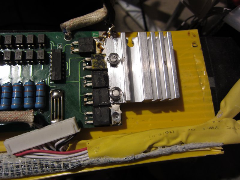
Ping said this bms is bad and he'll send me a new one..... do you think I can fix it?
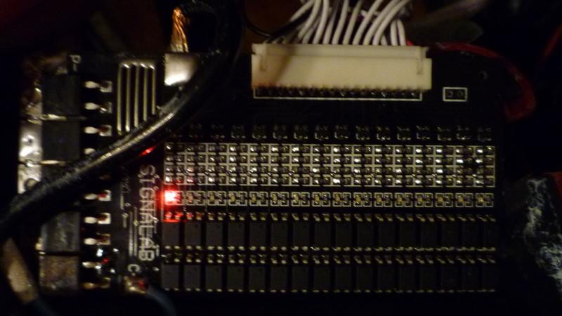
RWh0b.jpg

This light stays on -

After I fully charge the bms it 58v coming from the BMS.....and then I plugged it in to the controller. It immediately drops down to 7v. When I disconnect it from the controller it goes to 42v.... plug it back in and it drops down to 7v again.. unplug it and it goes back up to 42v.... Bypassing the bms and everything works fine.

All cells measure fine....except cell 1.... when measuring from ground to the first sense wire (cell 1) it is at 3.3 compared to 3.6...... weirdness.
 
When did you go Ping? I thought you were going to the dark side.
 
why can't you monitor the BMS? you should be able to measure cell voltages at the sense wire plug. why not unsolder one end of the led and pick it up, then see if the pack will charge. i have leds on scrap ones here too.
 
Dnmun I'm glad you saw this :D since you're the resident expert on these boards....

The problem started when I attached some 8s wires to the original 16s sense harness so that I could monitor the pack with cell logs... The cell logs work fine, and I just hooked up everything so that I can charge with an 8s r/c charger... although only at 3.5amps because of the 24 AWG sense cables...

What I meant by not being able to measure them was that it was a little bit tedious to solder 18 sets of wires to use the ping with the cell logs!

why not unsolder one end of the led and pick it up, then see if the pack will charge.

I don't understand what that would do... I mean the LED is on... so it's working....

BTW the pack will charge fully.... except that one cell with the LED always on was stuck at 3.3 (but I charged it up with the r/c charger)
 
I charged with 2.5v sla that stopped at 56v. Turned up the screw. I checked the sense wires all to many times, I an extra set of sense wires now white 16 pin would like to set it up to plug into those cellogs maybe break off a male 16 pin off an old bms. I have 4 in a box after 1.5 yrs.. Two work and the other are for Dr. Jickle. Ha Ha... I use my bike 6 days a week so I tried to keep it like light on the throlle, tried. My Ping takes a lot of abuse. Still works fine but not as strong as new. Maybe 400 cycles. Yes most all my bms problems were because up me tring to fix something else.
 
ok if you don't wanna pick up the led, why not unsolder and pick up the resistor to the left of it, just to make the led turn off, and then see if the pack will charge up and see if you can get that cell up to 3.6V like the others.

actually picking the resistor is better since it can be put back down, but i suspect the leds would die if they got that much heat.
 
Dnmun - I managed to balance the pack via the sense cables and main power cables with a balancing R/C style charger.... so no worries yet


I tested all the diodes and resistors on the bad channel and found that all but one diode compared the same to the good channels.


This diode reads the same from both sides.

I didn't test the ICs on the board because I don't know how! I'm a little bit nervous to replace something that small because I never have done anything like that on a pcb, and I'm also not sure it's the only problem or even what to replace it with.
 
Auraslip, If you make a pic. of what you need i have 40a. signalab for parts i tried to take off the 16 pin off the pcb. and the whit e palstic meled then broke (next time) . I wanted to use it for 2 8 celllogs.
 
I finally got my cells charged. The same led light was doing the exact same thing as yours auraslip (per my pm). Now the pack seems to be fully charged with all leds lit up, but when I put a load on it the voltage drops to 31.5v. If I put back on the charger all the leds are still lit up and I check the voltage on or off the charger it reads 45v (It's a 36v pack) So I am waiting on what ping says. :?:
 
Business wise, i would ask faulty BMS back too, just to be certain I am not getting scammed in sending more BMS...
 
Rather then start yet another Ping BMS repair thread, I'm going to commandeer this one. A Signalab BMS repair page would be good for the WIKI...

7/31/2011
The FETs on the my split pack 48V Ping V1 Signalab BMS got so hot that they unsoldered themselves from the BMS backplane and the bike didn't work so well like that.
I soldered them back on and added a heat sink. After putting it all back together and taking it for a ride around the block I found that the heat sink was already hot. Wow it's amazing it worked for 2 years like that. The heat sink definitely lets me push the Ping battery harder. The BMS used to shut down any time I accelerated a little too fast, even though the CA limits the controller to 20A (2C). This issue was always worse after I had been riding for a while so apparently this was due to the FETs heating up. Since I added the heat sink I have not had this issue.

Img_0302.jpg


8/27/2011
After a commute last week I noticed a strong burning electronics smell. That smell did not improve when I charged the battery, so I took it apart again. Those cracks in the FET do not look so good. Interestingly, the battery still seems to work fine, but I suspect not for long. The FETs must have been damaged when they got hot enough to unsolder themselves last month, or maybe I should have used a bigger heat sink. I see now that the offset FET is for charging, and the 4 FETs in a row are for discharging, so I definitely should have mounted the heat sink to the 4 FETs in a row rather than leaving one un-sinked. Duh. Note that the FETs have all identifying markings sanded off of them. This makes them more difficult to replace. I have sent an e-mail to the battery manufacturer Ping to get the replacement part number.

Img_0386.jpg


Browsing through all the threads dealing with fixing Signalab BMS issues, it looks like I can use at least one of the following FETs to repair this, maybe all of them.
TI BN7X51
irf3205
75N75
75NF75

Of all of these, it looks like only 75NF75 is available through mouser.com. If this is the correct part it looks better as it dissipates 300W as opposed to the irf3205 which only dissipates 200W. I'm assuming that the center pin is the same connection as the heat sink and that's why it is not used on the Signalab BMS?

What say ye?

-Warren.
 
Ping can send you a new bms in 10 days your 40amp. or even a 60amp. ( 10fet ) plugs right in to your white 16 wire plug. And if you have a C.A. to controll drain. I think 38 & 68 usd. maybe, there are signalab avaible in U.S. maybe someone will chime in.
 
I blew up my Signalab BMS recently so need to repair or replace. I shorted it out against the pack and i got a foul smell! Ping says that it will be around $47 for the regular BMS and $78 FOR THE 60A one.

Ambrose
 
Ping says "Yes, you can replace them with IRFB 4110 or 4310."

Cant find IRFB4310, but IRFB4110 is cross referenced to":
http://www.mouser.com/ProductDetail/STMicroelectronics/STP165N10F4/?qs=sGAEpiMZZMvECErq9cesgOd1AILV7hrINLJeLwInKEA%3d

Gate-Source Breakdown Voltage: 100 V
Continuous Drain Current: 120 A
Power Dissipation: 315 W

I'm ordering 5 of these FETs - $22

-Warren.
 
999zip999 said:
Found the old email 40a 47usd & 60a 78usd back in 09 plus shipping 19usd. Same Price ? Buy his single cell charger worked great.

He quoted shipping to me in the DC area of $15 for either one.

Ambrose
 
ambrose, you could mount the new output FETs on a copper heat sink and solder that back to the drain tabs on the BMS, then run the gate lead out on some small gauge, say 30 gauge wire for the gate voltage to the new output FETs, which with the heatsink could even be remote from the BMS, and then go clip the source leads off the mosfets that burned and solder your source legs of the new output FETs to the source traces on the BMS with some large cable. it is hard to get the old mosfets off if they burned the pcb usually.
 
Back
Top