Help me fix my 48V20Ah LiFePO pack

Glenn_M

10 W
Joined
Nov 3, 2009
Messages
82
Location
Melbourne, Australia
I have a 48V pack obtained with a ebike bought second hand. Not much is known about the pack.
I believe the KIT to be a Golden or Conhismoter kit - 48V 1000W.
Was working well then not ridden much over winter. Put in on the charger to top up the batts prior to riding again and found that it would not charge past 36V.

Checked the charger - outputting 60V
Checked BMS - 60V going through BMS to battery.
Disconnected BMS and charged batt directly - still no futher than 36V


Its a 15s pack, so using the same method as AW in his Volgood thread, here are the voltages at the balance wires:

1s- 3.6V
2s- 0
3s- 0
4s- 0
5s- 3.36
6s- 3.35
7s- 3.35
8s- 0
9s- 0
10s- 3.35
11s- 3.21
12s- 3.35
13s- 3.35
14s- 3.35
15s- 3.35

I am hoping for an easily repaired broken connection between the strings of batts.
Surgery to come :twisted:

Glenn
 
Patient prepped and ready for surgery
View attachment 4

Opening up to find 320 18650 cells and a puzzle of wires and connections
View attachment 2

A few obviously broken connectors were found
View attachment 3
View attachment 1

However, pressing down a set of the broken connectors saw sparks, smoke and a little burning - can see the black marks on the edge of the cell in the pic below where the tab was pressed down to make the connection. At that time decided to come back inside, read ES a bit more before making next move :oops:


Any observations or advice gratefully accepted.

Thanks,
Glenn
 
looks like you have 5 dead cell groups. no hope for those. probably you'd be better off just buying a whole new pack, unless you can find a source for cells that match the type and amphours of the remaining cells and are good at doing battery surgery.
 
Those 0V strings probably have bad cell(s) in them, given that the overall pack voltage is several cells low. If you're lucky, it's just one bad cell in each string that's slowly discharged all the others in that string, and they may be able to be slowly recharged. If they are cylindrical cells, this may work as it has for me; if prismatic (pouch) I don't know--I havent' had the chance to try that yet.

If you like, you can verify the balance wires are actually connected to the strings by carefully cutting or unwinding the tape holding the pack together, as shown in my Vpower and Volgood repair threads. Then physically trace which balance wire goes to which strings, and measure continuity from string to balance lead connector pin, and also measure voltages directly at the strings.

But I would guess that they are likely all connected fine, and it's cells that have failed.


What I would do is take either a current-limited single-cell style LiFePO4 charger or an adjustable-current-limit lab power supply (like the Sorenson I used), and charge the first 0V string, slowly, at 100mA to 250mA max, with the no-load voltage of the PSU set to 3.65V, until it reaches somewhere above say, 3V. Disconnect the charger/PSU and monitor the voltage. It will probably fall, likely fast enough to watch it happen.

If it starts falling, you can then do a binary search like I did on the Volgood pack repair, to find the bad cell(s) in that string, and leave them disconnected from the rest of the string. Reconnect the other cells, even if just temporarily (using little round neo magnets to hold wires on the cell ends, across the cut-gaps, for instance), and retry charging with the single-cell charger or lab PSU, again limited to the low current. If it reaches 3V ok, you could turn it up to maybe 500mA, and keep going till it's "full".

If you don't have a wattmeter that will tell you how much capacity you've put back into it, then just keep an eye on it till it gets to the voltage the PSU is set to (3.65V max); the current should start dropping as it nears that. If the current never drops even after it's reached that voltage, there are still other damaged cells in that string (possibly all of them, even though they don't self-discharge like the removed-cells did).

They may still work fine for your use, but they might get warmer during charge than the rest, or drop a lot more in rest voltage than the other strings, and not have as high a capacity as they should.

It is possible you'll have to remove *all* of the cells in each of the 0V strings, and replace them with new strings of cells. But I would bet that you can still use most of the cells in each of those strings, at least for a while.

Just be aware that there is always the possibility that the discharged/damaged cells may fail dramatically--it's just pretty unlikely with LiFePO4, and hasn't happened on my Vpower pack (yet) after quite a few discharge/recharge cycles.
 
Ah... some replies while I was posting the previous stuff. :)

The sparks when pressing down the tab is probably that the isolated cell(s) weren't discharged by the bad cells, and are still full enough to provide quite a bit of current trying to raise the voltage of the cells the tab was pressed to.

Or:

The isolated cell(s) are discharged completely (or never charged) and the rest of the group is putting out the current to try to raise the isolated cell(s)'s voltage. This is more likely because:


Those broken off cells actually look like someone was in there disconnecting those cells from the rest, especially with the X on there. ;)
 
@Amberwolf
The isolated cell was still at 3.65V so that's what I thought - it was passing much current to the dead cells.
The red marks are mine. Marking the dead strings then cells within the strings with obvious issues.

I have a Turnigy meter but no single cell charger or power supply.

@Jimw
Worst case and the 5 strings are toast, would still like to recycle the pack if I can. Lower capacity 48V pack still useful. Could also use 36V or 24V packs for various vehicles I've built for the kids. Converted a little ICE quad to electric :D

Don't like throwing things away that are only partially stuffed

Glenn
 
Another little discovery, although only 15 cells linked to the BMS, there are actually 16 cells.
One has never been connected via a balance wire to the BMS. This is the first cell on the positive side.

 
THe top and bottom of the pack are connected to the BMS via the main pack + and - wires, so they don't have to ahve a balance wire, too. ;)


Surely there is someone in the area you could borrow or rent a lab supply from. Doesn't have to be much of a supply, either--at most it needs to put out 3.65V at 500mA, so a 5V 500mA supply would work.

You could even build one, if you were up to that, with various schematics found on the web for such small supplies.
 
the reason they are disconnected is because the poor design and workmanship on these vpower packs causes the strap to short out to the case where the strap crosses the edge of the cell. you can find the burn marks if you look. 15 wires is ok, the top of the #16 is connected through the red wire on the BMS and the bottom of the #1 is connected through the black wire.
 
Well, you learn something new everyday :wink:
Have been meaning to get a 18650 charger for a set of bike lights I have been building so I should get onto that.
I have an adjustable power supply on my vellman multimeter/powersupply/soldering station. Will that do? It's not current limited though (rated 1.5A peak 2A). Can select 3 or 4.5V


Alternatively I could *modify* a USB cable / adapter. Should output 5V @ 500mA
However - finding replacement cells is likely to be an issue as well so perhaps I should just convert to a 36V20Ah pack?
Thanks for the help guys, appreciated.

Glenn
 
Whatever you use should to be current limited, even if it's an addon limiter you've built for it. If it isn't, a few things could happen, though I don't know which one actually would:

Nothing; cell just charges up really quick.

Nothing, cell doesn't take a charge, or discharges really fast.

Cell is damaged further by charging too fast from it's dead state.

Cell voltage being so low essentially shorts out the PSU, and blows it up.

Same, but PSU can sustain the current and voltage ok, and the cell overheats from charging too fast, and cell leaks, catches fire, or blows up.

PSU fuse blows as soon as it's hooked up to cell.

Etc.


I do know that charging the dead cells up from nothing using low currents can work. I don't know what doing it with high currents will do; havent' tested that. :)

Also, unless you plan to sit there for hours or days watching the multimeter to ensure it doesn't charge too high a voltage, you'll want to be able to precisely set the top voltage of the charger/PSU, so the cell *can't* be overcharged.
 
Hmmmm, not that I'm adverse to experimentation and trying things out.......but limited knowledge, equipment and time plus the burning things down aspect of playing with LiFePO suggests reducing the voltage of the pack to 11s (can be used on the kids 36V motoX bike) plus repurposing the salvageable 18650 cells into batt packs for my lights is the go.

So the thread will continue in this light.

Now also on the market for a 48V batt pack. Thinking 16Ah Headways might be the go.....

Glenn
 
OK, so a day with multimeter, soldering iron etc sees me with:

A box of dud 20Ah strings. These will be pulled apart to recycle good cells into little 7.2V packs for my DIY bike lights
View attachment 2

Also two 18V 20Ah "halves" of a remaining 36V20Ah pack. Hopefully my soldering hasn't damaged the cells.
View attachment 1

Now these halves will be placed saddle bag style under the front "tank" fairing of this:


With a 36V 500W DD hub that Cell_Man had laced into a 20" rear wheel for me.
Now just need a new BMS and Charger......

Don't suppose the 48V BMS can still be used or modified to work with the 36pack?
Cheers,
Glenn
 
I'm sure it *can*, but I haven't ever looked into *how* to do that.

It's possible that nothing need be done but disconnect the balance wires that are not used. It may be "smart" enough to determine it's actual pack size and not alarm or cut out for the missing section at the top of the pack.

Failing that, I expect that simply removing the daughter board on the BMS that the second balance plug goes into will turn it into a lower voltage version, for however many series cells would be left on it's balance plug (which I think is one or two more than the daughter board's plug). But that isn't likely to be enough for what you want.

On the Ping Signalab BMS, it's possible to (IIRC) just short across specific optocoupler pins of unused channels to make a lower voltage version, so something similar is likely to work here, too. It'd require tracing out the circuits and reverse engineering it to determine where to do that, though, or experimentation.

That last is one reason I did not remove the bad string from my own pack when I found it's original problem, but instead ran it with just the missing cell from teh string. I *might* be able to figure it out with enough time, but I also might damage something in the process, which I can't afford to replace. ;)
 
Depends on the BMS, a lot of the V power BMS'es are reconfigurable, there are link points that you just solder across.
 
heathyoung said:
Depends on the BMS, a lot of the V power BMS'es are reconfigurable, there are link points that you just solder across.

OK - Sound like BMS surgery next :lol: I'm game!
Will disassemble and get some pics and post later

Glenn
 
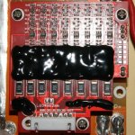
Well, here is the BMS.
It's a PCM-L16S40-240 which seems to be available from a number of Chinese resellers. Whoever makes the thing is not evident.
Details can be found here http://www.ayaatech.com/shop/?type=detail&id=532

Now as there is no markings like "Solder here for 10S" or "Hey Glenn, this is the bit for 36V" I am a bit stuffed now.

Some other BMS's on the site are labelled 10s-16s suggesting that the number of cells in series is configurable to some extent. This one is labelled 16s only.
Appear to be a few comments on ES about these (none good it would seem :( ) so doesn't look good......

View attachment 2
View attachment 1
 
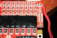
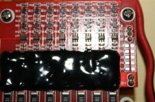
See the solder points on the top red board? They will be where you have to jumper it. ie. bottom LHS of IMG_3067

Get a closer picture of the red 'daughter' board - especially that section.
 
heathyoung said:
See the solder points on the top red board? They will be where you have to jumper it. ie. bottom LHS of IMG_3067

Get a closer picture of the red 'daughter' board - especially that section.

@Heathyoung here you go. A 2*5 matrix of pads labelled 1s to 5s top to bottom. What do I do too them?

Glenn

IMG_3069 (Medium).JPG
IMG_3074 (Medium).JPG
IMG_3075 (Medium).JPG
 
Actually, I think those are 11S thru 15S, which makes sense given it's a 16S BMS--for 16S you leave them all alone.

If you need to use it one cell group short, solder across 15S.

If you need to use it for only an 11S pack, solder across 11S.

I suspect the main board underneath it might also have those pads, but I don't have access to mine at the moment without taking the pack apart off the bike.
 
You might well be right there Amber.
On the bottom PCB there are two other sets of pads labelled 6s and 7s also.

Do I not have to solder across the pad for EACH cell I don't want to use? As in to reduce from 16s to 14s for example, solder across BOTH the 15s and 14s pads?

Your post above implies soldering across one pad only. That is to reduce to an 11s pack solder across the 11s pads ONLY

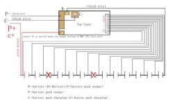
The original 16s pack is now a 10s so I need to 'remove' 6 strings from the series. Doing that will mean soldering across the pads on both the main and daughter boards. Seeing as soldering the pads closes the circuit to the +ve trace thereby removing that cell. As long as the cells are rewired in the correct serial order (my) logic says should be fine.

Here's what I mean (ignore the fact this is a 13s schematic)
schematic.jpg

What do you think?

BTW - thanks for the assist guys. Wouldn't have made it this far without the help.

Glenn
 
Thats correct - solder the ONE pad you want the pack configured for. Ie. 12S

Reconfigure (MOVE) your cell taps to suit the configuration you need, do NOT solder more than one jumper or you will have smoke. Do not use that schematic. Ie. Tap 1 to cell 1, tap 2 to cell 2 etc etc Tap 11 to cell 11 - DO NOT SKIP CELLS.
 
Back
Top