can i parallel old and new Nimh?

monster

100 kW
Joined
Jun 17, 2007
Messages
1,411
hi

i have lots of batteries now but i want to know if i can parallel old and new Nimh if they are both fully charged. the old Nimh was over charged a couple of times, is worn out, and has a higher voltage. i have no diodes. will it take equally from both and empty one before the other?

i will charge separately of course -i have seen what happens with parallel charge!
 
monster said:
hi

i have lots of batteries now but i want to know if i can parallel old and new Nimh if they are both fully charged. the old Nimh was over charged a couple of times, is worn out, and has a higher voltage. i have no diodes. will it take equally from both and empty one before the other?

i will charge separately of course -i have seen what happens with parallel charge!

I did this routinely, but I did 'bin' the old battery capacities in charge groups of 24v, this way I would prevent cells from going <1v

Always check the weaker pack by small groups of 6v to id week cells. I ran 120 bs.com 10ahr cells this way, and occassionaly a bad cell needed to be replaced.

Nog
 
i found that the over charged battery actually went up in volts. i don't think there are any <1 volt cells in there. assuming this is the case is it then safe?

when i parallel the fully charged batteries should i expect any current to move between batteries? -this will stop fast right?
 
You need to talk to the guy at ebikes.ca about getting a schottky diode shunt.

http://www.ebikes.ca/store/#ElectricalAcc

This is the gadget that prevents batteries that are squirrelly about being paralleled from frying each other.
 
monster said:
i found that the over charged battery actually went up in volts. i don't think there are any <1 volt cells in there. assuming this is the case is it then safe?

when i parallel the fully charged batteries should i expect any current to move between batteries? -this will stop fast right?

Normally, the current will stop very fast. The problem is if one string gets a shorted cell, the current might not stop. The diode setup will prevent any current, but does impose a small voltage drop.

Just for a test, you could try connecting the two packs with an ammeter between them to see how much current actually flows. I don't think it will be much if the packs are anywhere near matched.
 
cheers fechter. i was thinking the same thing about the amp meter check. i didn't think about shorted cells. i will not be using this as my standard configuration because it will be too heavy, its just for when i want to do 25 miles. therefore i think i can get away without diodes. if a cell does short a 1.2v difference between packs of 72v should only result in a 2 amp flow which would not be disastrous i think? (from my experience with charging) i could get away with just 15amp fuses to prevent bigger cell shorts from killing the pack. zener diodes would be ideal of course.
 
Just a word of caution about parallel connecting NiMH packs. I built a pack using two sets of 36V, 3.7Ah, RC model type packs. They are connected so that they discharge in parallel via a dual Schottky diode. This works fine. I'm in the middle of building a custom charger, but wanted to charge the packs up anyway.

Last night I hooked both packs up in parallel, using another dual Schottly diode to isolate them from each other, and connected them to a constant current power supply, set at about the 0.1C rate (750mA for a 7.4Ah pack). I guessed (wrongly) that this would be safe overnight, as it should take about 12 hours or more to fully charge the packs (they were fully discharged).

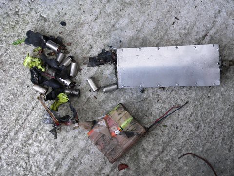
I was woken up early this morning by a loud bang from my study, where the packs were on charge. I got out of bed, ran to the study and was confronted with a smoking battery pack. I managed to get the pack outside just in time, within seconds the cells exploded violently and caught fire.

2235176774_381d55c5d2.jpg


I've now checked things over and can confirm that the charger is fine, it's still giving out the set current of 750mA. The Schottky diodes are fine also, as is the "good" pack in the above picture. The wiring was all well-protected, and there was plenty of good insulation around each pack, so a short in the pack was extremely unlikely to have been the cause. My best guess is that the two 36V sub-packs didn't current share equally, so one managed to charge much faster than the other. After nine hours on charge the faster-charging sub-pack went into thermal runaway.

The rate of acceleration of the fire was frighteningly quick. It was maybe two or three minutes from me waking up at the first bang, to me realising the problem, getting out of bed and disconnecting the pack. It was just smoking at this time. By the time I'd carried it through the house and got it out of the back door it was showing signs of an internal fire. Within seconds of getting it outside the end of the pack blew off, scattering burning cells over a couple of feet. This was followed by an intense fire and further cell explosions.

All in, not a sensible thing to have done and one from which I hope a few lessons have been learned. I came perilously close to burning the house down, a minute or two later and my study would have gone up in flames.

Take care with any battery experiments, folks!

Jeremy
 
I've now had a chance to look at the cells more closely. I can't see any obvious sign of a "hot spot", wiring or insulation failure. The "good" sub-pack is reading about 39.6V now, some 30 hours after the incident. I'm discharging the "good" sub-pack pack at the moment to try and see how much capacity it still has, as this may give an indication as to whether there was a charge imbalance.

Both sub-packs were built from newly purchased 12V 3.7Ah RC model sub-C packs that seem to have come from the same batch. Each 12V unit had been charged once and then discharged to 1.1V per cell, at a low rate, just to get all cells into a similar condition before I built the pack up. The complete assembled pack had been sat for about a week or so before I got around to charging it the day before yesterday.

My best guess is that both 36V sub-packs charged fairly equally for a while, with one perhaps taking 10% more than the other, due to minor internal differences, or perhaps the wire lengths (the sub-pack that failed was the one with the shortest leads by about a foot). The dual Schottky diode I used to isolate cross-currents was fitted to the charger, perhaps it may have been better fitted close to the sub-packs themselves.

The pack that reached full charge first started to heat up and rather foolishly I'd not bothered to wire up the thermistors I'd put into the pack to a cut-off circuit. I'd not bothered to fit thermal fuses or a thermal cut-off switch to the pack either, which was also pretty stupid (I've just ordered some of these for the replacement pack.....). Once it started heating up it went into thermal runaway, even though the charge it was accepting was no more than 0.2C (assuming it took all the charge and the other pack had virtually stopped accepting anything.

The cascade failure was most probably initiated from insulation failing around the cells as a result of the very high temperature. It looks like the thin heat shrink sleeve fitted over each cell quickly splits when it gets hot, allowing the cell cases to touch and short.

The "good" sub-pack actually looks fine, apart from some soot damage and a bit of heat damage at one end (which has damaged the cell sleeves quite badly). None of the vents seem to have blown, and the cells don't seem to have distorted in any way. I won't be using these cells in the bike, as I've no idea what long term damage has been done, although I may salvage some for use as cordless power tool replacements.

The next question is really whether I replace them with more of the same, or go for something different, like LiFePo. I've got a limited space on the 'bent to fit the pack, as I want to keep the installation fairly stealthy. I don't need much capacity, as I'm only using a little TongXin motor for hill-assist. I may email Ping or Yesa and ask about getting some individual cells to make a discreet under-seat pack up.

One thing's for sure, I'm never going to charge a pack up in the house again!

Jeremy
 
yer the over-charge of a paralleled nimh pack is frighteningly fast. when you think of battery charging most things that happen are SLOW, however over-charging of paralleled nimh packs is FAST. my paralleled nimh incident, heated a pack up to 150*C in 20 minutes. i think its exponential!
 
Jeremy Harris said:
Last night I hooked both packs up in parallel, using another dual Schottly diode to isolate them from each other...

No, they weren't isolated at all.

I can't imagine any arrangement of diodes that they would be doing anything other than dropping some voltage.
You can use diodes to isolate two sources from a load, but not two loads from a single source.
Maybe I just don't see it.
Fech & the brain trust, what say you?

But the parallel part of the equation aside, I might have made the same mistake assuming that it's safe to charge a *single* pack @0.2C for 10 hours.
That's because I'm used to NiCd which are more tolerant of overcharge.
Even though I've read that continuous charging of NiMH at anything more than 0.02C can damage them, it didn't sink home like your mishap did.
A continuous three-quarters of an amp is quite a lot actually if you think about it.


Anyway, for the benefit of anyone in the future that will read this.
If you want to attempt charging nickel chemistries in parallel,

DON'T DO IT!
DON'T DO IT!

and
HELL NO,
DON'T DO IT!!!!


You can't cheat these things.
If you want to charge more than one pack you're only options are:

1. Use a separate charger for each sub-pack of serial connected cells with the packs isolated from each other completely.
2. If you only have the one charger, then resist temptation & charge one at a time. You save more time this way than rebuilding your house.
3. If you're the compulsive type & absolutely HAVE to charge them together, then disconnect the two sub packs from being in parallel & hook them together serial if you have a charger of high enuf voltage to do that.
A pain in the ass to constantly do that, but pls bear in mind the consequences.

I think any other electronic solution would cost about as much as a second charger anyways.
Just to be clear, this all applies only to the charging side of this thread's question.


For discharging in parallel, I have yet to hear of anyone getting into trouble & (I hesitate to say this cuz someone will prove otherwise) is reasonably safe to do so.

This is only for illustration, but if you were to take a fully charged brand new pack & parallel it to a fully discharged old pack with the same number of cells, what's the worst that's gonna happen?
A relatively high current will flow briefly as the discharged packs voltage comes up to equalize with the fully charged pack & current will stop flowing.
Basically a battery makes for a piss-poor charger becuz you require several volts above the terminal voltage to keep the current flowing.
Even in the worst case scenario of a shorted cell, the voltage differential won't be enuf to maintain much of a charge current.
I suppose the really worst case scenario is if you have a pack with multiple shorted cells, while possible is rather unusual & you'd probably spot that b4 hooking them up.

So even without isolating diodes the risk is low.
With diodes, the packs can be old or new, different chemistires with different voltages even.
The usefulness of doing that my be questionable, but the safety is assured.

Sorry if this sounds like I'm dumbing it down.
Clearly people aren't appreciating the scope of the risk involved, I've learned something here too.
Perhaps because it's not lithium people let down their guard.
Also for every one person that has the guts to post his mistake for others to see, that represents who knows how many others that have had the same thing happen but don't have the courage to share their experience for others to benefit from.
As more people enter into this field, it would only take a few burnt houses, or better yet a whole condo or apartment complex to get torched that the whole game could change overnight once the legislators get involved.
 
So ... don't wire them up permanently ... use andersons or something similar and disconnect while charging each separately, I gather?

I'll keep that in mind when I finish up my A123 pack.
 
The diodes I used were a pair of 20A, 100V Schottkys, wired so that the diode anodes were connected to the sub-pack negatives. The monolithic diode pair I used was connected with a common cathode to the charger negative. The two battery sub-pack positive leads were connected together to the charger positive. The diodes should have been very closely matched for Vf, as they were a monolithic pair.

As far as I can see, the diodes would effectively isolate any cross-currents from passing from one sub-pack to the other, which was the original intention. They did this job well, but it was almost certainly why one pack accepted more charge than the other. My best guess is that the terminal voltage of the "good" sub-pack, as seen at the charger, was slightly higher than that of the sub-pack that failed. This may have been as a consequence of a slight mismatch, or even just the slightly greater voltage drop on the longer wires to the "good" sub-pack.

The isolating diodes exacerbated my problem, as they allowed one pack, the one with the lower terminal voltage, to take the bulk of the charging current. The diodes effectively cut-off the charging current to the higher voltage sub-pack. Had I just connected the two sub-packs in parallel, then the terminal voltage of both would have been the same and I'm sure that the problem wouldn't have arisen.

Jeremy
 
Jeremy Harris said:
The diodes I used were a pair of 20A, 100V Schottkys, wired so that the diode anodes were connected to the sub-pack negatives. The monolithic diode pair I used was connected with a common cathode to the charger negative. The two battery sub-pack positive leads were connected together to the charger positive. The diodes should have been very closely matched for Vf, as they were a monolithic pair.

As far as I can see, the diodes would effectively isolate any cross-currents from passing from one sub-pack to the other, which was the original intention. They did this job well, but it was almost certainly why one pack accepted more charge than the other. My best guess is that the terminal voltage of the "good" sub-pack, as seen at the charger, was slightly higher than that of the sub-pack that failed. This may have been as a consequence of a slight mismatch, or even just the slightly greater voltage drop on the longer wires to the "good" sub-pack.

The isolating diodes exacerbated my problem, as they allowed one pack, the one with the lower terminal voltage, to take the bulk of the charging current. The diodes effectively cut-off the charging current to the higher voltage sub-pack. Had I just connected the two sub-packs in parallel, then the terminal voltage of both would have been the same and I'm sure that the problem wouldn't have arisen.

Jeremy

I guess I was a little too glib when I said they weren't isolated at all.
The way you have it connected does indeed isolate the packs during discharge & is correct for preventing cross currents.
I meant that the point where you hooked in the negative lead of your charger, the packs aren't isolated at all during charging.


The negative of your charger shouldn't go to the common cathode.
You've effectively bypassed the diode because they are always on, functioning like a wire except for the small voltage drop.
So I would disagree the diodes exacerbated the problem or that hooking in direct would have been better.
They way it's hooked up, the charger is already directly connected, so the end result would have been the same.

The way to make use of the isolation diodes for charging in the manner you have the diodes connected, the negative lead of the charger needs to go to the junction of the pack negative terminal/anode of one of the dual diodes.

:arrow: Repeat: not to the common cathode :!:

In this manner the diode you are connected to is functioning to isolate the charger from the second pack.

Now you're free to also connect the negative lead from a second charger to the other anode/negative terminal junction of the second pack while maintaining isolation between the two packs & chargers.
All the positive leads from the chargers & packs can then remain tied together in common.
I'm sorry, there's no simple way of getting around that you have to have separate chargers, or charge one pack at a time.
If anyone knows otherwise, I'm all ears.

The benefit of the isolation diodes during charging is primarily for convenience.
So that you don't have to constantly plug & unplug the packs to separate them for charging.
By wiring a pigtail to each schottkey anode/pack negative junction point, along with a wire to the positive common point & another for the NTC sense line, you can then bring these lines out of the pack into a suitable single connector housing to form a convenient charge port.
Then an adapter cable to break back out the lines into separate connectors for each of your chargers.

Remember that everything gets reversed if you use common anode diodes. :D


Just to clear up one point for kbarret, the hazard warning was with respect the parallel charging of nimh/nicad only.
That's becuz the nickel chemistries are somewhat unique in that they exhibit the unusual phenomenon of accepting more current once they are fully charged, a kind of negative resistance.
This is backwards from most other chemistries, lead & lithium among them, which taper off accepting current as they approach being full.

I've heard that A123 don't require separation or even isolation diodes for parallel charging or discharging, but that may be becuz the BMS looks after that, so don't quote me on that.
Each chemistry has it's own personality & caveats.
 
I cannot understand your thinking when you say the sub-packs aren't isolated by these diodes during charging, but maybe I'm missing something here. OK, my second degree is in EE, and was taken well over 30 years ago now and has been little used since, but I think I'm getting confused all the same. I've attached a sketch below showing how my packs were wired (for charging) to the variable constant current charger, just in case there's some confusion about the wiring scheme I used.

Putting some numbers on this makes it easier for me to understand. Let's say that sub-pack A is at 40V and sub-pack B is at 39V. Let's assume the diodes are perfect, with no Vf. Let's also assume that my constant current charger is a true constant current (which it pretty much is at these current/voltage levels). The output voltage of the charger will match that of the lowest voltage sub-pack, so will be 39V. The diode at the base of sub-pack A will be reverse biased by 1V (as sub-pack A is sitting at 40V, so will stop current flowing to that pack).

As far as I can see these diodes seem to make a pretty good charging isolator. Even with real-world diodes, the isolation principle above holds good, as far as I can see.

The discharge wiring uses the same type of dual Shottky diodes, but connected with the anodes to the sub-pack positive connections and the common cathode to the controller main fuse. The sub-pack negatives are connected together to the controller negative during discharge.

Jeremy
 
I knew I shoulda waited for a drawing.
When you mentioned a second set of dual diodes I didn't quite know what to make of that.
Here's the problem.


Jeremy Harris said:
The output voltage of the charger will match that of the lowest voltage sub-pack, so will be 39V. The diode at the base of sub-pack A will be reverse biased by 1V (as sub-pack A is sitting at 40V, so will stop current flowing to that pack).


The trouble with that arrangement is that the lower voltage pack may in fact be the one that's already fully charged.
If it's gone past its peak voltage, it will continue to drop ever lower becuz of negative delta V.
The diode has no way of knowing if the 39V represents prior or after the peak, so the first pack to reach full charge will become the lower voltage pack & absorb almost all of the charge current.
That's the same situation as having no diodes in there at all.


Believe me I've scoured the web looking for an end run around negative delta V for some easy way of parallel charging nimhs.
All I've found so far is in the Panasonic NiMh handbook they hint that if you need to parallel charge to contact them & they will design something for you, so at least I know that it's somehow possible.
If it were doable with a 'dumb' circuit using only diodes, I sure someone would have done it by now.
 
OK, we're now singing off the same hymn sheet - your conclusion matches my original one! Good to know that all that stuff I learned many years ago is still sort of OK.

My mistake was to assume that the sub-packs would balance, because, as you say, I forgot about the fact that the cell terminal voltage can drop slightly once past the peak charge point.

As an extra little snippet, I noticed that some of the burned-out cells looked intact. It turned out that the "end" cells in each 12V sub-sub-pack looked to be unaffected by the fire, except for having the insulation burned off and looking a bit black and sooty. This is largely because the soldered wires dropped off in the heat, so these cells couldn't short any more. All the other cells were fitted with welded tabs, so discharged to destruction via case shorts.

I decided to check them out, so snipped them away from the rest of the debris, put a meter on them and was a bit surprised to find that they were all sitting at 1.25V. I've just finished a discharge test to 1V on them, at around 0.3C, and found that they were holding about 2Ah (they are rated at 3.7Ah). I'm now charging these cells up again (very carefully!) and will do another discharge test to see what their true capacity is. I'm guessing it will be way down on the rated capacity, but the fact that they are working at all shows what tough things these little cells are (if not abused to the point of exploding............).

Jeremy
 
if in stead of diodes you used light bulbs then that would limit the current going to each battery. it would not prevent an overcharge on the one that peaks first, but it would limit the extent of that overcharge. -you could then terminate by timer switch.

this would not ballance them of course.

but newer charge in nimh parallel, for it is the love that dare not speak its name!
 
When using light bulbs in that way you're basically building a crude constant current source which he was already using an actual CC power supply.
It just needed to be set to one tenth lower current to a safe trickle level but who's gonna wait 50 hours.
I'm just floored at how intolerant NiMH are to overcharge compared to NiCd, which under the same conditions of 0.2C would probably have fared better.
I've definitely been spoilt by the kind of abuse nicads will put up with, both charge & discharge.
Only A123's from the sound of things seem to even come close.
 
I wouldn't be surprised if most of the cells from the toasted pack are just fine. Obviously they were capable of discharging at a high rate. The short probably only lasted a few seconds before the jumpers melted.

With two strings in parallel, as soon as the first one reaches full charge, the voltage drops as pointed out. This causes the fully charged string to hog all the current from the charger. The diodes prevent the other string from discharging into the fully charged one (this would be even worse), but won't prevent the current hogging.

You really need a separate constant current source for each string. Monster's light bulb idea would be a good approximation to a CC source if it has the right voltage drop. There are a number of other more sophisticated constant current circuits, and you could have a number of them sourced by the same power supply.
 
Do you forsee any problem with implementing a current mirror to prevent current hogging & force the individual strings to share equally?
At least that's the wild goose I'm chasing.
If you don't hear from me in a while assume it didn't work out.
Where's that pic of roasted GP (Gold Peak).
 
Current mirror? Hmm... don't see why that wouldn't work, although if you're going to do that, it would be just as easy to have separate CC sources. They make pretty smart Ni chemistry charge controller chips with delta V charge cutoff. One of those for each string with temp sensors would be even better.

Fried_guinea_pig.jpg
 
monster said:
if in stead of diodes you used light bulbs then that

Hi,

I have been parallel charging two NIMH packs with a harness that uses diodes, light bulbs and with thermistors on both packs. So far this has worked fine, but since Jeremy's experience I have been a bit more careful with it. AFAIUI (from some other discussions with Jeremy) the root problem was that his charger would supply more current (0.2C I think) in the trickle charge phase that one pack alone would like to receive.

That is the same in my system. In fact its the reason I wanted to charge two packs - to share the current and get it down to a safe level in each pack. I do have thermistors in each pack and in theory it ought to shut down if either pack gets hot. But..... Its not ideal and really I would say you need a more sophisticated circuit, by which time of course its easier to just have two separate chargers

Nick
 
Back
Top