DIY ebike Chargers

Alan B

100 GW
Joined
Sep 11, 2010
Messages
7,809
Location
San Francisco Bay Area, USA
For some time I've been thinking about the potential for a barebones high power charger. I see that the Electric Car folks are already well along on this with DIY 10KW chargers and 25KW on the way.

So should we have a similar scaled down unit? Something sized for ebike batteries. On 120V we can get 1.5KW, the folks with 240 a bit more.

These designs are small and light for their power level. They are far beyond the basic "bad boy" chargers and are regulated. They rectify the line, charge a cap, switch into an inductor with an IGBT, filter with a capacitor, and control the works with a little microprocessor like an Arduino. At the 240V 10KW level they cost about $600-800 in kit form. At the ebike level they will be even less expensive. They have open source designs and software that could be modified for ebike use. At ebike power levels it might be okay to use a big FET or two instead of the IGBT, but either should work.

Someone already done this? Any interest in it??

Here is one of the DIY EV Charger threads:

http://www.diyelectriccar.com/forums/showthread.php/10kw-60a-diy-charger-open-source-59210.html

Also found an ES thread on a simple "dirty charger" that has some simpler (and more dangerous) charging ideas:

http://endless-sphere.com/forums/viewtopic.php?f=14&t=19658

Dangerous charger is also similar:

http://endless-sphere.com/forums/viewtopic.php?f=2&t=31428

Charging with unstabilized power supply:

http://endless-sphere.com/forums/viewtopic.php?f=14&t=31384

Rectified Mains charge lead:

http://endless-sphere.com/forums/viewtopic.php?f=14&t=30664
 
I've been thinking of building a portable charger, that design route looks promising. Would it be possible to add power factor correction to this design?

Intersil has a new chip out that they are calling a cell balancing system.
http://premier.intersil.com/auto/EV_HEV.asp
The ISL78600 battery management system provides the high accuracy needed across the full battery operating temperature range for precise, state-of-charge measurements to extend vehicle driving range and the life of high performance Li-Ion batteries. To accomplish this, each ISL78600 device utilizes a 14-bit temperature compensated data converter that scans 12 channels in less than 250 microseconds.

To achieve the highest possible reliability for intra-system communication, the ISL78600 utilizes a high noise immunity and transient tolerant communication scheme. This fully differential daisy-chain architecture allows the use of low cost twisted pair wiring to stack multiple battery packs together while protecting against hot plugging and high voltage transients. Additionally, The ISL78600 allows for easy connection to microcontrollers via either a 4MHz (or 2.5MHz with Filter enabled) SPI or 400KHz I2C interface.

Key Features

6 to 12 cell voltage management
Supports full range of Li-Ion cell chemistries
Cell voltage measurement accuracy ±2mV
VBAT measurement accuracy ±72mV
Cell voltage scan rate of 20μs per cell
Proprietary Daisy chain communications system
Robust EMI performance
Excellent system transient resistance
4MHz SPI interface
Integrated system diagnostic functions:
Cell over and under-voltage
Over temperature
Open cell monitoring wires
Open temperature monitoring wires
VBAT and VSS connection integrity
Voltage reference function
Oscillator function
64 lead TQFP package
Passive balancing

I have to get some samples. They have also released the IS78601 that acts as a stand alone backup for redundant cell monitoring.
 
Why not just use that existing open-source charger for a starting point? Since we don't need as high a charging current, and probably not as high a chargng voltage, the actual power-conversion stage(s) don't need such large components, but the software itself should be easily adaptable, from either Valerun's version,
http://www.diyelectriccar.com/forums/showthread.php/10kw-60a-diy-charger-open-source-59210.html
the older one that Jack Bauer is building, (with one codedump attached here, for instance:
http://www.diyelectriccar.com/forums/showpost.php?p=270573&postcount=272 ) (more data buried in his build thread:
http://www.diyelectriccar.com/forums/showthread.php?t=35098 )
or from Simon Rafferty's original designs.
http://www.diyelectriccar.com/forums/showthread.php/200-build-your-own-intelligent-charger-36627.html
 
A good 2 - 5KW charger would be great for fast charging a reasonable nanotech pack.
I would like anything that could take up to 230V @20A single phase input because bigger is better...
Realistically up to 2-3KW would probably be a good goal for ebike use as a fast charger although a really small <500W ultra compact one would be handy as an onboard charger.

Those car chargers seem to be non isolated, for an ebike pack where it is harder to protect wiring than a car.
I would think an isolated design would be much safer.

Could also be pretty spectacular on 240VAC if the switching device were to fail short into a <100V lipo pack :lol:

I've thought of doing something about a high power charger but I'm too busy with my other projects so i'll just watch this thread with interest for now.
 
amberwolf said:
Why not just use that existing open-source charger for a starting point? Since we don't need as high a charging current, and probably not as high a chargng voltage, the actual power-conversion stage(s) don't need such large components, but the software itself should be easily adaptable, from either Valerun's version,
http://www.diyelectriccar.com/forums/showthread.php/10kw-60a-diy-charger-open-source-59210.html
the older one that Jack Bauer is building, (with one codedump attached here, for instance:
http://www.diyelectriccar.com/forums/showpost.php?p=270573&postcount=272 ) (more data buried in his build thread:
http://www.diyelectriccar.com/forums/showthread.php?t=35098 )
or from Simon Rafferty's original designs.
http://www.diyelectriccar.com/forums/showthread.php/200-build-your-own-intelligent-charger-36627.html

Precisely.
 
Ricky_nz said:
A good 2 - 5KW charger would be great for fast charging a reasonable nanotech pack.
I would like anything that could take up to 230V @20A single phase input because bigger is better...
Realistically up to 2-3KW would probably be a good goal for ebike use as a fast charger although a really small <500W ultra compact one would be handy as an onboard charger.

Those car chargers seem to be non isolated, for an ebike pack where it is harder to protect wiring than a car.
I would think an isolated design would be much safer.

Could also be pretty spectacular on 240VAC if the switching device were to fail short into a <100V lipo pack :lol:

I've thought of doing something about a high power charger but I'm too busy with my other projects so i'll just watch this thread with interest for now.


I also like the idea of having several, a larger one for home that could use either 120/240 input, and a second compact unit that could do 120V 15A input on the bike. A 500W super compact unit would also be a great option. A scaleable design. The car folks mention that for 240V input the minimum output is about 50V due to PWM resolution. So a 120V version might have a 25V lower limit for the same reason unless higher resolution PWM is available.

Isolation would be nice. Would require a high frequency transformer and isolated drive and power for the switching element. Raises complexity a bit. Would be good if the design could go either way. I've been thinking about having the micro test the load for isolation before the charge cycle starts and refusing to charge if the load is not isolated.

Properly fused a shorted switching device should be manageable. Perhaps a programmable SCR crowbar for insurance? The output polarity protection diode would help here also.
 
Unisolated make it cheap, isolated forward converters that are wide range adjustable require specialised magnetics and design know-how.

Its very easy to blow the crap out of your devices when designing forward converters, they are a nightmare.

For a less crap design - look here: http://www.neon-john.net/Induction/Roy/Buck_Converter.htm

It uses a proper IGBT driver, that also takes care of output current limiting, easy to get components, and is nicely adjustable.

There are a few things that are bad about this design - the input caps are under spec, for this sort of current you need a good, low ESR cap with a high ripple current. (ie. 7.5A @ 600uF - not cheap - you need to series/parallel 4 to get here) I'd also be putting a decent cap on the output for ripple suppression and overshoot.

The inductor also needs to be specified - the design fails to mention the size, but my calcs put it at 170uH for Vin of 300V and Vout of 150V. His other design uses a 300uH from memory, but this is far from optimal.

Its a good start though, I'm drawing up a PCB to support this design, with multi-voltage compatibility (ie. 120/240VAC), with current limiting.
 
heathyoung said:
Unisolated make it cheap, isolated forward converters that are wide range adjustable require specialised magnetics and design know-how.

Its very easy to blow the crap out of your devices when designing forward converters, they are a nightmare.

For a less crap design - look here: http://www.neon-john.net/Induction/Roy/Buck_Converter.htm

It uses a proper IGBT driver, that also takes care of output current limiting, easy to get components, and is nicely adjustable.

There are a few things that are bad about this design - the input caps are under spec, for this sort of current you need a good, low ESR cap with a high ripple current. (ie. 7.5A @ 600uF - not cheap - you need to series/parallel 4 to get here) I'd also be putting a decent cap on the output for ripple suppression and overshoot.

The inductor also needs to be specified - the design fails to mention the size, but my calcs put it at 170uH for Vin of 300V and Vout of 150V. His other design uses a 300uH from memory, but this is far from optimal.

Its a good start though, I'm drawing up a PCB to support this design, with multi-voltage compatibility (ie. 120/240VAC), with current limiting.

Thanks for your comments. You seem to have some experience in this area.

A question. Since we are charging batteries, not making a power supply, it would seem to be easier to use a microprocessor to drive PWM to the IGBT via a proper driver. Why bother with the more complicated power supply chips? A micro will be needed anyway to handle all the charging parameters, and getting all the extra parts working right is nontrivial. The micro can read the voltage and current and adjust the PWM for the low bandwidth feedback loop required for battery charging. It can also implement many equipment protection features easily, and ramp things up nicely at the start.
 
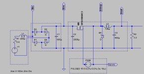
That car charger was up earlier and then I started to play with the idea to make a more eBike oriented charger. I also decided that it was a god project to try out spice for the first time . So I downloaded LTSpice which is free and came up with:

ss1.JPG

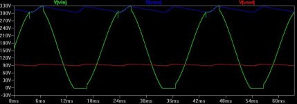
And simulation:

sw1.JPG

Now there are lots of problems with the model but maybe it can be a starting point? If some spice gurus can make suggestions I would be happy to add them and maybe we can reach a place where we have something worth prototyping?

I agree that a MCU approach would have advantages over a dedicated SMPS chip. Integration with BMS and also keeping track on how much power has been put in is probably essential to most people.

Naturally it should all be open source and all models etc shared (it there only was a wiki or something....)
 
Alan B said:
Looks like a decent start!

Great! A couple of things that should be fixed/considered for starters:

1. The mains model does not behave properly, it does not go down to -240 volts as it should. It probably doesnt matter but it bugs me.

2. What should a proper model of a lithium battery be?

3. Is it worthwhile to go for synchronous (replace diod with mosfet) ?

4. I have used transient simulation so far, would AC be better?
 
The AC is referenced to circuit ground through the diodes, so that causes the end you are graphing to be pushing on ground at the 0V end. I would not worry about that.

I suspect that synchronous mode has less value at these high voltages, and adds some dangerous complexity with opportunity for shoot-through. The diode is simpler and the loss is a small fraction of the total power at these voltages. But it would be good to get input from folks who have more experience with these types of designs.

One question is FET vs IGBT.
 
I found this article quite good : http://my.ece.ucsb.edu/Bobsclass/194/References/NonIsolated/Buck/Buck%20Converter%20Design%20Demystified%20606PET25.pdf

I have been thinking that a FET is better than a IGBT since FETs can switch faster and that allows smaller inductor and capacitor. However for europe with 240V mains and 340 peak (plus some margin) IGBTs may be a better choise, for US 120V (169 peak) FETs come out on top.

This article: http://www.irf.com/technical-info/whitepaper/choosewisely.pdf places this application pretty much in the "gray area" where it "depends" :)
 
Both of those papers are good reads. The IRF paper on choosing FET vs IGBT looks very familiar but perhaps is updated due to newer devices. Still the conclusions are very similar - FET for under 250V, IGBT over 1000V and the grey area in between. New devices have changed the details though.

Since the 10KW IGBT 240V design is available we should probably focus on the other end of the scale, and starting with a 500W FET design might be a good learning experience. A physically small 500W 120V charger that works as a bulk charger and integrates well with the fechter/goodrum BMS would be a useful item for ES. A 1500W 120V design might not be much larger. But the failures might be a lot more expensive.
 
I fully agree, start with a basic 500w charger that can scale with "just" improved thermal handling and better components.

One thing that I have given som thought is how to supply the MCU/PWM part. The DIY EV chargers just use a ready PCB power supply component but I think that is to expensive and I think isolation is of the board anyway.

I came across this app note http://ww1.microchip.com/downloads/en/AppNotes/00954A.pdf and is looks just the thing.

Also it mentions detecting when the mains crosses zero. Is there an advantage to chopping the input voltage at the zero crossings for a buck converter or is that for some other SMPS topology?

Anyway, maybe another part of the puzzle.
 
I think we can use a PC power supply for prototyping. That should cover the input side and produce sufficient 170VDC for 500W or so, depending on the rating of the supply. Remove the circuitry beyond there, or just ignore it and tap out the bulk DC. The AC inlet, switch, fan, and case are also useful. The fan is probably DC so we'll have to power that.
 
Thats not a bad approach. Except for that I recently threw out 6-7 broken ones. Never throw away anything, never listen to the wife. :evil:

I just noticed from the app note that in fig 12 they show a rectified resistive circuit and since the rectifier is there anyway all that is needed to power the MCU is a zener, a resistor and a cap.... Neat.
 
Would probably use a arduino and LCD shield to prototype this:

http://www.ebay.com/itm/High-Quality-Arduino-Uno-ATmega328P-PU-Module-ATMEGA8U2-AVR-USB-Cable-Board-/180749806106?pt=LH_DefaultDomain_0&hash=item2a15872a1a
http://www.ebay.com/itm/LCD-Keypad-Shield-Arduino-Duemilanove-Freeduino-B-/370561856615?pt=LH_DefaultDomain_0&hash=item5647353467

Less than $40 total, not the end of the world to toast a few during development.

So basically building a buck converter shield...
 
pelle242 said:
Would probably use a arduino and LCD shield to prototype this:

http://www.ebay.com/itm/High-Quality-Arduino-Uno-ATmega328P-PU-Module-ATMEGA8U2-AVR-USB-Cable-Board-/180749806106?pt=LH_DefaultDomain_0&hash=item2a15872a1a
http://www.ebay.com/itm/LCD-Keypad-Shield-Arduino-Duemilanove-Freeduino-B-/370561856615?pt=LH_DefaultDomain_0&hash=item5647353467

Less than $40 total, not the end of the world to toast a few during development.

So basically building a buck converter shield...

Looks reasonable. I've been doing a couple of Arduino projects lately So I have a Uno here. In the past I did micro projects the hard way, with various micros including PIC and AVR and various programming boards and dongles. The Arduino is an easy way to get into AVR and C/C++. So a good choice, also similar to what the car folks are doing which may be useful. Can probably share some code.

Perhaps find a box that will house the Arduino and bolt to the side of the PC power supply box. Keep all the high voltage in the PC box so the Arduino box is finger safe.
 
One thought is to use a rugged plastic box for the micro such as an otterbox. I have a couple that are about the right size, and clear so you can see the display. Mount one pushbutton through the box for start/stop. To adjust the settings, open the box and get to the joystick, etc inside. For day to day use just hook up and 'start', or make it auto-start.
 
IGBT's vs Mosfets - the SOAR curves make IGBT's for this app a no-brainer.

240V vs 120V - use a doubler topology for 120V, and full bridge for 240V, same as you would use for a PC power supply (hence the 120/240 switch on the side).

Power supply for the PWM controller (ie. bias supply) - since it isn't possible to do a bootstrap design, use on of the readily available 85-300V switcher units that are designed to replace the old 'sugar cube' mains transformers - they are 90% efficient, 2W 5-15V power supplys. Using something like a PC power supply is just plain lazy. So is an amplified zener reg (as per a Vectrix charger - YUK).

Microcontrollers vs PWM chips - yes you could, but why? Electrically noisy environment, hot - not the place for a micro at all... I wouldn't be worried about frying micros during design, but rather vapourizing tracks off PCB's and turning IGBT's into 3 legs soldered onto a PCB.
Horses for courses as they say, and a locked up micro driving an IGBT for a buck topology would make for a fairly spectacular failure mode!

The 10Kw version is badly designed - it could be a quarter of the size if it was designed and built properly, and not constructed like a valve radio.

Power supply design at this level of output is interesting to say the least - get it right with the right components (ie. TL494 - its in pretty much every SMPS ever built for a reason) before faffing around with micros.
 
Sounds like a nice and practical setup.

Have been looking around for components. I remember that they had trouble finding the inductor for the EV charger, pullde them from huge UPS units or welders or wound them themself. I think their issue is since they use a IGBT they cant switch that fast and then the inductor has to be big.

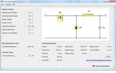
I found this tool from TI: http://www.ti.com/tool/powerstage-designer

Playing arund a little and it is obvious that faster switching is the key.
ti_buck1.jpg

Question is if 500Khz is realistic? Will that instead mean that the MOSFET must be very expensive?
 
I haven't taken any PC power supplies apart yet. So they have voltage doublers? Interesting. Do PC power supplies use IGBTs? I would think whatever they used is probably what we need to use. Perhaps even re-use what's there? Heatsink, check.

500 khz is not hard for an FET. Requires a good driver though, and good diodes. Might not want to go that high.

Since we want to have a programmable user interface with cell type, voltage per cell, number of cells, max current, shutoff percentage, time limit we need a micro. If we have a micro what's the SMPS chip needed for? Seems like extra parts.

For equipment protection I'm thinking an SCR crowbar across the input fuse. Output voltage ever spikes up too far, blow that fuse. Set the watchdog timer on the micro to shut everything down if it gets stuck, and use a real PWM output so it can't get 'stuck' on. I suspect the RC chargers work this way and they manage it up to a kilowatt.

Winding the inductor is not a big deal.
 
Alan B said:
I haven't taken any PC power supplies apart yet. So they have voltage doublers? Interesting. Do PC power supplies use IGBTs? I would think whatever they used is probably what we need to use. Perhaps even re-use what's there? Heatsink, check.

500 khz is not hard for an FET. Requires a good driver though, and good diodes. Might not want to go that high.

Since we want to have a programmable user interface with cell type, voltage per cell, number of cells, max current, shutoff percentage, time limit we need a micro. If we have a micro what's the SMPS chip needed for? Seems like extra parts.

For equipment protection I'm thinking an SCR crowbar across the input fuse. Output voltage ever spikes up too far, blow that fuse. Set the watchdog timer on the micro to shut everything down if it gets stuck, and use a real PWM output so it can't get 'stuck' on. I suspect the RC chargers work this way and they manage it up to a kilowatt.

Winding the inductor is not a big deal.

Yep, PC power supplies (the ones that have the voltage switch on them) use a voltage doubler topology - have a look at this project http://sound.westhost.com/project65.htm to see how it works in practice.

They don't use FET's, they use transistors.

Higher the frequency, smaller the magnetics BUT the more critical the components. Making a big slow ugly SMPS is several magnitudes easier than a multi-Mhz, 100W/cm2 unit :)

No furthur comment on the Micro - good if you are using something like lead acid,with multi-stage equalization etc. but for a CC/CV unit, it only really needs to be a power supply with current limiting.

Winding an inductor that won't saturate at high currents, and change its inductance greatly over its operating current range is more complex.

Pre-done versions are cheap - http://www.coilws.com/index.php?main_page=index&cPath=208_212_229_113

The IGBT's the DIY guys use are not suitable for the application - square peg - round hole. There are IGBT's approaching and exceeding mosfet switching times - problem is, you have the VF losses. So you balance VF losses vs. crappy SOAR curves of mosfets.

80-125Khz is a good compromise between size, layout complexities (there is a reason why PC power supples are 44Khz) component losses etc.

At 500Khz you approach AM RF frequencies, and designing for RF starts to get interesting. Its a black art, I used to fix FM transmitters and they never behave as you would expect (or model them) to do so. You also start to find that you are building an RF transmitter rather than a power supply and this is NOT a place for sensitive microcontrollers - diode junctions become radio recievers.

I've (accidentally) made power supplies that would wipe out radio reception in a 1Klm radius. Not desirable. :oops:
 
Back
Top