My distributed Battery Management System project

nlc

1 mW
Joined
Mar 2, 2008
Messages
18
Location
France
Hello everybody, is there or moderator which can tell me if I am authorized to talk about the BMS system I develop ? I primary develop it for my personal use but because my job is electronic hardware/software developer all the design is done in a professional way, and I think I will try to sell my BMS in a close future when everything will be finished. I present it briefly for now.

Thus my project is a distributed BMS to supervise and protect lithium chemistry pack of EV. The BMS is based on a slave board on each cell, to measure voltage and temperature of the cell, and a "master board", which receive the voltage and temperature of all cells and can take decision (stop charge, stop discharge, datalogging, display, and so on).

The slave boards are finished and are already fully industrialized, I can launch a production at any time.
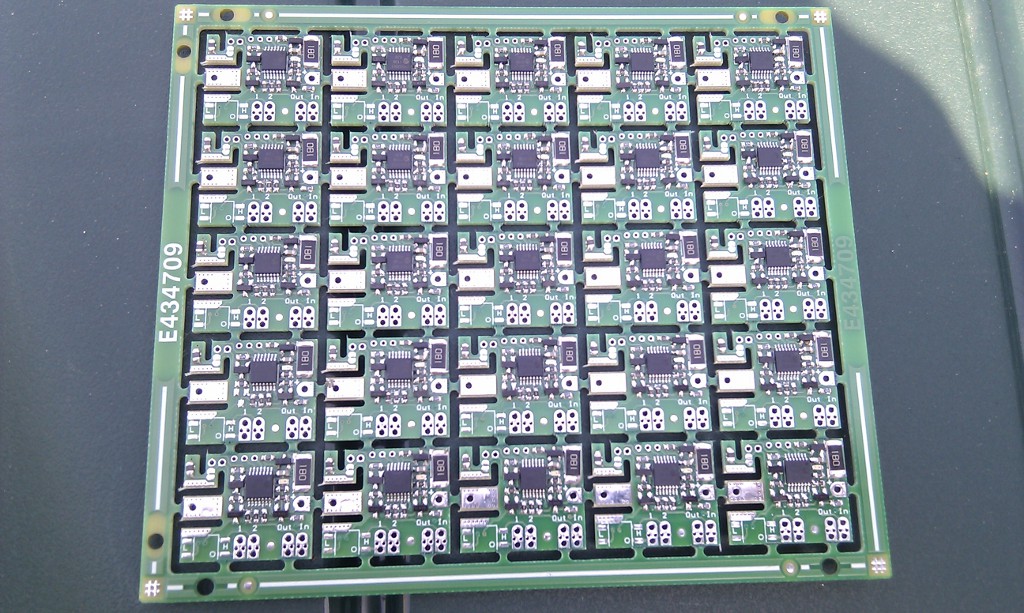
Sometime image are better than words, here are the slave boards for voltage and temperature measurement (size of the board is 24x20mm) :

bms_slave_flanc_3.jpg


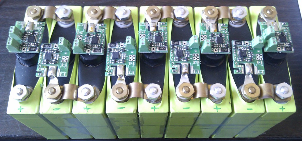
Mounting on a small pack for development test, without wire for now :

bms_pack_1.jpg


After wiring (1 wire between cells and 2 wire for the first and last cell connected to the master, here my computer through a very simple interface), it give this :

[youtube]http://www.youtube.com/watch?v=k3qjPXCfs6M[/youtube]
http://www.youtube.com/watch?v=k3qjPXCfs6M

Note : the music comes from a toy of my children, not from the BMS :lol: :lol:

My goals are to propose a very powerful and precise system at the lowest price as possible, and open the protocol I developed to let the possibility to diy guys to use these slaves boards in their own project if needed. Thus it become possible to read voltage and temperature of all pack's cell (up to 255 cells) with just a free UART (RS232) ! Because this slave boards are just slave, they have absolutely no configuration for threshold, they just send the cell voltage and temperature to the "master", and it's the master's job to decide what to do depending on the chemistry (li-ion, li-po or lifepo4), for example stop charging, stop discharging, activate the balancing on any cell, and so on.

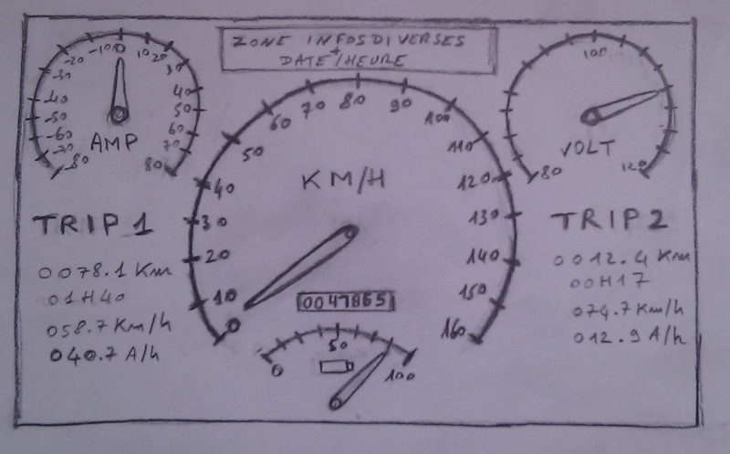
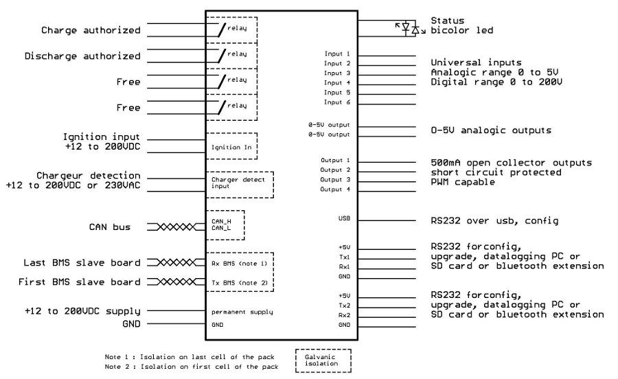
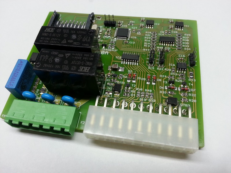
As I said slave board design is finished, now I work on a master/display board. It will be a sort of powerful cycle-analyst, with same "basic" dash board monitor functions, but improved with the cells supervision/management, SoC, integrated datalogging, status outputs to stop charge/discharge, color TFT touchscreen, etc...

Regards
 
nlc, shouldn't be a problem, and welcome to the board. Feel free to use this thread to talk about all the technical details of your BMS. Your blood sweat and tears. False starts, bad ideas, good ideas, and things that went right or wrong for you.

As said when it comes time you want to sell items, start a new thread in the For Sale New Section with prices, availability and such.

I'll throw out a question: Have you tested the system in a vehicle with a couple of hundred amps being slung around by the controller? Is the system immune to the EMI?
 
They sure look pretty :) How are they with vibration? A lower profile would probably make for a more robust system.
 
Looks slick, but does it balance? I would think that is also important other than monitoring it. It would do this only during charging.
 
Ok, thank you very much, thus I can answer questions :

Alan B said:
What technology do you use to communicate between the boards?

It's UART RS232 based : Tx of "master" board is connected to Rx of the top cell, Tx of a cell is connected to Rx of the next cell, and on the last cell (bottom cell), the Tx is connected to the Rx of the master. Each cell is connected to next cell with just one wire. Of course it's not RS232 level !
The master sends a request/command frame and the frame pass through each cell, and each cell concatenate their data to the frame and calculate new checksum. When the frame arrive to the master, it automatically knows the number of cell on the pack and gets the voltage and temperature of each cell. Also, because each cell is connected to the next cell, there is a automatic addressing of cells, absolutely no configuration at all on slaves. With this daisy chain functional operation, it's impossible to have a malfunctioning of one slave board and destroy the cell because the master will not receive any frame and can detect the problem immediately. In this case, to locate the problem it's very easy, just look where the LED doesn't flash on the pack and the problem is located here !
From communication speed point of view, if you imagine a pack of 255 cells, I can read all 255 voltage/temperature every 1.5s 8)

bigmoose said:
I'll throw out a question: Have you tested the system in a vehicle with a couple of hundred amps being slung around by the controller? Is the system immune to the EMI?

Not for the moment, but it will be the case don't worry about that, before sell anything there are still many test to do. And I plan the propose a preferential price for first people which want to try the system. For EMI, 2 things to take into account :
- The board must be maximum immunized, I think it's the case because design is simple, efficiency (and the high current don't pass through the board), but need to verify that
- In case of very powerful EMI spike, if the system or communication is perturbed, everything must restart correctly when the EMI spike is finished. For this point it's the case, the slave software is very robust, in case of communication problem everything is managed, and in case of big crash and freeze because of big EMI spike, board automatically restart, thank to watchdog timer.

jonescg said:
They sure look pretty :) How are they with vibration? A lower profile would probably make for a more robust system.

For the profile in my 10Ah pack it was mandatory for me to mount the pod this way, but normally the pod is inserted directly in the board edge. For vibration, my board is much smaller than every expensive commercial product which use same connection principle, so it can only be better ! But there is also the possibility to not use the pod for GND electrode and also use a wire, and directly stick the board to the cell.

mvly said:
Looks slick, but does it balance? I would think that is also important other than monitoring it. It would do this only during charging.

Yes, it balances, the master can switch ON/OFF the balancing of any slave at any time. It's not a big balancing (approx 200mA) because the board is small, but it's not really a problem because with all independent voltage of all cells, it become possible in the master to precisely determine the characteristics of each cell and then have a smart balancing which begin its work during the charge and not at the end of charge when the cell reach the HVC threshold. But for those who think 200mA is too small current balancing, I put 2 big solder pad under the board to solder an optional external power resistor to boost the balancing current. The switch I use on the board can commute 4A :wink:

t3sla said:
Brass tax.
How much we looking at $??

Brass tax ? Sorry I don't understood the expression, what does it means ?
The nude slave board price will be around 9€ (~12$ ?), and a little more if you need the pod and the screw terminal

In the next message I will give all the slave board technical specification
 
Technicals specifications of the slave board :

- Board size 24x20mm
- Direct mounting on cell, with optional GND pod, or wire
- Voltage range between 2.3V and 5V
- Simultaneous sampling of all cells : the voltage measurement of all cells in the pack corresponds to the same current value
- 10 bits ADC but with oversampling technical voltage measurement is 13 bits equivalent, thus <2mV resolution. Precision comes from reference voltage used and is 0.25%
- Integrated NTC resistor but possibility to bypass it and add an external 15K NTC (solpads on board) to deport the temperature measurement if needed
- Integrated 200mA balancing (18r resistor), and possibility to add an external power resistor (2 big solders pad on the board), to boost the balance
current up to 4A (but ~16W dissipation become a lot of dissipation :mrgreen: )
- Master can independently control ON/OFF the balancing of any cell. Will permits smart balancing during charge and not only at the end of charge. It compensates the small balancing current, a 200mA balancing during a 10h charge is 2Ah balancing !
- Automatically wake up when communication is engaged by the master, and automatically goes in sleep mode when there is no communication
- Current consumption on cell is ~15µA in sleep mode, and <10mA in working mode. In sleep mode with 15µA the slave board will consume 1Ah on the cell in....7 years :lol:
- Easy wiring, only 1 wire between each cell, and 2 wires from first and last cell to the master. Optional screw terminal for slave board interconnection
- Complete isolation between the pack and master (first and last cell are the same than other but with an additional optocoupler mounted to have the galvanic isolation with the master)
- Easy debugging, if master doesn't receive the final communication frame, just look where LED doesn't flash, the communication problem is located here !
- Daisy chain system also works if all slave boards are connected to the same cell or same power supply (thus on same gnd potential), very useful to verify if all slave boards are okay before real mounting on the pack !
- Protocol will be open to permits anyone to directly use these slave boards without master board on its own design to supervise the pack and control balancing of any cell
- The daisy chain can support up to 255 cells, in this configuration maximum read rate is 1.5s


I think I don't forgot anything, I will complete if needed !
Regards
 
Very nice! Modular, Isolated, and salable are very desirable traits for hackers (and in general really)

Are you willing to tell us what Chip you're using? Is this designed only for LiFEPO4, or could is it software adjustable?
 
The slave boards are just slave, they just measure voltage and inform master, it's the master job's to do what is necessary to do depending on the chemistry and threshold configured. It's why this system is highly modular and can work with any chemistry in the range of 2.3V-5V. Thus it can be mounted on li-ion, li-po or lifepo4 without any configuration in the slave boards.

The chip used is a microchip PIC microcontroller
 
and the major advantage of these would be that the wires coming from the slaves will just be data cables meaning if they get damaged they wont set your pack on fire.

Nice job I like the design.

what output current can the slaves handle when wired into your pack?
 
chilledoutuk said:
and the major advantage of these would be that the wires coming from the slaves will just be data cables meaning if they get damaged they wont set your pack on fire.
Absolutely, there is no high voltage in the 4 cable which go out of the battery pack.

chilledoutuk said:
what output current can the slaves handle when wired into your pack?

The output current doesn't flow thought the slave boards :wink:
 
Oh I see these are for detection and balancing of the cells and the master unit controls the current flow from the pack Very smart indeed.

The biggest question I have is what kind of drainage current do these units put on the cells when not in use?

That is one of the biggest issues for bms systems aka battery murdering systems and also the problem with having thin cables connected to high power
cells with no protection should they short if crushed from bad cable routing.
 
chilledoutuk said:
The biggest question I have is what kind of drainage current do these units put on the cells when not in use?

When there is no communication from master, slave boards go in sleep mode and draws about 15µA on the cell. Thus a slave board will draw 1Ah from the cell in 7 years ! :lol:
I think the cell will be empty before with its own autodecharge !!

chilledoutuk said:
That is one of the biggest issues for bms systems aka battery murdering systems
Yes it's why I worked to have the sleep current as low as possible.

chilledoutuk said:
and also the problem with having thin cables connected to high power
cells with no protection should they short if crushed from bad cable routing.

In this case with the mounting topology used, there are no cable which start from an electrode and travel away from cell. Each slave board are directly mounted between the +/- electrode of a cell, and just a short wire travel to the next cell. And this wire is a current limited communication wire, thus a short circuit will have no consequence.

And the 4 wire which get out of the pack (2 wire from the last cell and 2 wire from the first cell) are isolated and only travel car chassis referenced low voltage. If you install these 4 wire to never have these wire travel on the pack but directly arrive on the first and last cell (as on my video for example), it's really difficult to have a short somewhere 8)
 
To proof your RS232 communications link it might be an interesting test to take your test set up shown in the videos, have it running, and place a universal electrical motor with a sparking commutator (like a drill with a cord) near your communications circuits and investigate the stability of your communications link. Stick as many drills as you have right on top of the link and see what happens.

You can also do this with a cordless drill, and bring a ground lead out from the battery pack and attach it to various places on your boards and see what effect that has. Just a couple of tricks to ring out any potential problems before things go into full production.
 
Yes good idea ! I have a drill percution which do a lot of spark, I will try !

Today I finished a board to test the ability to drive a TFT screen in RGB mode (with no integrated driver) with direct connection to the external bus of a microcontroller, and using and external SRAM on the bus as framebuffer.
It's work very well, I use DMA to refresh the TFT data with the framebuffer content, and I am able to have a 20Hz refresh rate, more than needed for this kind of application.
I also tested a complete framebuffer update (blue/red color), which consist to change the value of all 130.560 words (16 bits) in the framebuffer, because it's a 480x472 4.3" TFT screen. It works well, it takes 50ms to fill the entire framebuffer ! A small video, I switch blue/red every second :

http://www.youtube.com/watch?v=Ny4uQXYD0wA&NR=1
 
Today I tested your EMI immunity experiment with a big drill, with the master (my computer) requesting slaves datas every 200ms (5 Hz refresh rate) to have a lot of communication data in the wires. But with the led flash of 50ms every valid received frame, on the video the flash seems to be completely erratic !! In fact it's not the case, and there were no error, you maybe will see "erreur BMS = 0" on the laptop screen, but you need good eyes !!!

http://www.youtube.com/watch?v=UmJaK8qrxyQ

On other side, I think about the display, need the opinion of every interested people. I think something like that can be great ?

ev-analyser-display-1.jpg


- The ampmeter with real time battery pack current (when touched, switch to WATTs)
- A generic zone for display various message, date and hour, etc...
- The voltmeter with real time pack voltage. When touched, switch to a new page to monitor all cell voltage and temperature (with an histogram for exemple)
- The vehicle speed and total mileage
- The "fuel" gauge, based on amp hour which enter/leave the battery pack, and pack capacity configured. When touched, display another interesting informations : total amp hour provided by the pack, total number of charge cycle, etc..
- 2 independent trips informations : distance, duration, average speed, amp hour used, average W/Km or W/Mi. When touch on the zone, display secondary information of the trip (percentage of regen, etc...)
 
My work on this BMS project continue, the slave board are totally finished (hardware+software), now just need real dynamic testing on a pack.

I currently work on the master board, because I think I will not sell any slave board without a master board to use them. This master board will be very evolutionary with a lot of possible functionalities. :)

Here is the general diagram of the board :

mini_master_archi_en_3.jpg


The schematic design is almost completely done, in some days I will reach the routing step :)

I found a great enclosure for this master board :

bms_boitier_1.jpg


bms_boitier_2.jpg
 
Some month are passed, and some news : I simplified the master board, to begin with something simple, here is the pcb, I sent it in production yersteday :

Capture-31.png

Functionalities are :

- 12V supply
- Ignition input (to startup the master in discharge mode)
- Isolated charger mains detection input (to startup the master in charge mode)
- One relay contact output to indicate that charge is authorized
- One relay contact output to indicate that discharge is authorized
- 2 status Led output
- 2 free open collector outputs
- Serial port for configuration/firmware upgrade/bluetooth module option connection (for supervision and data-logging with a smartphone)
- BMS interface to first and last BMS slave board (2 to 255 slaves possible)
- 2 digitals/analogic inputs
- 2 analogic outputs (0-5V), to drive gauge for example
- Can bus
- SD card connector (to save datalog file for example)
 
This is great news. Cant wait for more on how your system performs. I dont know if it is relevant but perhaps it is possible to include individual cell SOC graph. bar? That would be good to see how cells behave under load to monitor for bad cells?
Any info on pricing for the main unit?
 
First the first software version I will only provide datalogging of cell voltage VS discharging current. It's already a godd way to see how performs cells under load. But in future release we can imagine a lot of integrated functionnality and beautiful thing on the touchscreen of an Android device !! :D

For the price of the master, I will know that soon, but I do everything I can do to have the lowest price as possible for a professional electronic grade. But I will not have big production quantity, so I think it will be around 120$, maybe a little less.
 
Using N-chan mosfets with large dies could replace the relays. I use a simple charge pump circuit to bring their gate to 15V. You can also parallell smaller mosfets as much as you want, in this non-critical application avalanching and such isn't a problem.

My BMS basically has the same functionality as yours, just with lesser part count and rough samplings going all the time, and precise samplings requested once there is no power being asked for.
 
Back
Top