methods LVC/HVC/Parallel -> documentation thread

methods

1 GW
Joined
Aug 8, 2008
Messages
5,555
Location
Santa Cruz CA
This is a total work in progress....

The link below will take you to a plethora of lightly commented pictures that should assist you in your travels with my LVC/HVC/Parallel system. In the following days/weeks I will fill in the pictures with a few thousand wordy paragraphs... Until then just use your imagination.

Please!
If anyone has pictures share them here. The good, the bad, and the ugly. I think we all understand at this point that this aspect of your build is just going to be messy and your best bet is to cover it up. But... do your brethren a favor and unbutton that tight blouse for us just a bit. Show us your goodies and we will be forever grateful.

Methods LVC/HVC/Parallel Manual

Feel free to chat in this thread.
Builds
Pictures!!!
Issues
Suggestions
Feedback
Complaints
Introduce your product that is better (so I can steal it...)
whatever. My threads are open to all.
(but I do bark and I do bite)

-methods
 
would you someday sell as part of your LVC/HVC some sort of voltage converter such as the one showed by DrBass?
http://endless-sphere.com/forums/viewtopic.php?f=14&t=29024&hilit=dc%2A%2A%2A+charg%2A

It would be great to have a complete integrated system that we could connect to any power supply.
 
Nice! Just when I needed it most!

I think I found an error in this pic, about 20% down the page:
image016.jpg


* * * EDIT * * * Error fixed, above pic correct. Thanks!
 
DesignerDan said:
Great documentation! It definitely cleared things up.

Imagine what it will be like when I actually add words :mrgreen:


MattyCiii said:
I think I found an error in this pic, about 20% down the page:....
HVC VCC should be LVC VCC in on the middle wire, yes?

Mmm... good job! That is a mistake for sure. I will fix it up right away.
EDIT: I can see that you hyperlinked the picture - it appears to be corrected above.
Thank you for pointing that out - the only thing worse that no documentation is incorrect documentation!
(so how about those history books from school....)


cwah said:
would you someday sell as part of your LVC/HVC some sort of voltage converter such as the one showed by DrBass?
http://endless-sphere.com/forums/viewtopic.php?f=14&t=29024&hilit=dc%2A%2A%2A+charg%2A

It would be great to have a complete integrated system that we could connect to any power supply.

I will check this out....

-methods
 
I'm finally getting around to building the pack and bike for my wife and just came upon something that I previously did not plan out.

With the LVC and throttle retard, has anyone found a clean way to make the pack easily removable ? To clarify, since this bike is for my wife, I would like to make it such that she won't have to unplug a throttle cable as well as the battery. Without the throttle retard cable, currently, the battery hooks up to the bike with prongs that slip into place when the battery is dropped into it's place.

Here's a pic of the receptacle I am talking about. This part is on the battery and a 3 prong is on the bike where the battery mounts.

Giant%20eSuede%20-%20Battery%20Plug.jpg


2 of the prongs are currently used as Pos and Neg on the battery hookup. The third prong seems to be an alignment piece as there are no corresponding wires on the battery side.

My idea so far would be to add 3 RCA-style (or another connector) to get the 3 throttle wires. Or, if I could somehow use the 2 unused prongs + another connector.


Idea's?
 
Hi All,

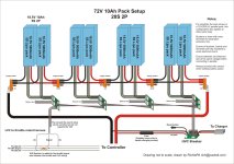
Here is a diagram I have been working on to help people understand how to put together battery packs with the V2 HVC/LVC/Parallel boards.
I have uploaded it as a large .jpg but you'll find the .pdf is a much sharper image when zooming in.
View attachment battery circuit inc hvc lvc boards.pdf
battery circuit inc hvc lvc boards.jpg
Hope this helps.
 
RichiePA said:
Hi All,

Here is a diagram I have been working on to help people understand how to put together battery packs with the V2 HVC/LVC/Parallel boards.
I have uploaded it as a large .jpg but you'll find the .pdf is a much sharper image when zooming in.
View attachment 1

Hope this helps.


Great job! It is very clean and easy to understand. This should help out a lot of people, including myself. I drew up some small diagrams to help myself understand it all better, but this is tits!
 
RichiePA said:
Hi All,

Here is a diagram I have been working on.....

This guy is a hero - will you just look at the quality of that drawing?
I am secretly plotting to have him come work for me....

-methods
 
Wow! Damn RichiePA! Nice drawing! Makes everything super clear and easy in a single drawing. Nice job!
 
Thank you Richie! Much nicer than I have ever done and very easy to understand. Saved it for one of my bad days when I am not able to understand these things so well.
 
Lots of werq into that Mr. Methods makes me tired just looking at the pictures. ;^) Thanks much for making things more easy to understand for those of us who need it.
 
I have come up with a small mod for the HVC_Breaker boards that I am considering a MANDATORY update.
It is super easy, simple, and cheap.


HVC Breaker Fix.jpg

Please have a look at that picture.
I need you to install a capacitor between the second pin of the relay and V+
It can be nearly any value so long as it is rated for at least your pack voltage. A 100V 1uF ceramic would be perfect.

For those of you that can surface solder I suggest an 0805 100V Ceramic butted up next to the 10M in that picture.
0.1uF or 1uF is fine - whatever you have in the box.

For those who can not surface mount solder I propose grabbing a cap anywhere (like $0.10 at Radioshack) and carefully soldering into the relay pin and the main voltage rail. Ceramic caps are not polarized.

For domestic customers in the US I can offer a 24 hour turn-around service if you want to send your board to me. I would use the opportunity to upgrade your board to the latest design. Not big changes, but a few tweaks:

1) Gate bypass cap added. This turns the mosfet on MUCH faster and greatly improves reliability in noisy environments.
2) Lower gate resistance to 5M. This doubles the running current of the circuit from 10uA to 20uA but it adds margin for parts variability
3) Relocate 15V zener. On my latest model I have found much greater noise immunity by mounting the gate zener right on the gate rail

These three changes improve the performance of the board enough that it can now be used as a discharge control device. It can handle the short-circuit inrush presented by a controller and it can withstand the flyback voltage from breaking 40A.

So - if you are a DIY guy PLEASE just add this capacitor ASAP to your circuit. Feel free to email me with questions. Go ahead and drop the 10M Gate resistor to 5M if you like by placing a second 10M resistor in parallel with your Cap. Dont worry about relocating the gate zener if you are just charging and not discharging with the circuit.

For my international customers I am trying to figure out a solution that does not cost a fortune... Shipping is $17 for me.... This is more than my mark-up on the parts and it will result in a great loss for me if I try to offer a repair service (not to mention it will take forever). Of course I will do this if someone wants me to - but I figure any guy who can hook up this stuff must be able to solder in a capacitor - right?

Anyhow... yea...
We need to add a gate speedup cap to turn the mosfets on faster.

I am going to post this in a few places. If you know anyone running one of my HVC Breakers please notify them that this changes needs to happen.

thanks,
-methods
 
RichiePA said:
Hi All,

Here is a diagram I have been working on to help people understand how to put together battery packs with the V2 HVC/LVC/Parallel boards.
I have uploaded it as a large .jpg but you'll find the .pdf is a much sharper image when zooming in.
View attachment 1

Hope this helps.

That is nice!

Where can we find the cooper busbar as connector in your picture?
 
cwah said:
That is nice!

Where can we find the cooper busbar as connector in your picture?

Thanks, you can buy busbars lovingly made by myself at jozztek.com http://www.jozztek.com/shop/7-busbars-wiring

You'll need the "equally spaced busbars" x (the number of packs your connecting in series -1) for connecting the packs in series and then a set of terminal busbars for the + and - end of the total pack.

With the busbar terminal ends you can specify where you would like the M8 threaded hole orientated for connecting your pack out to the rest of you bike.

Use the drop down selectors to choose how many packs in parallel you will require this will re-calculate the price. :D

All our busbars are handmade to order so if you have any special requirments let us know.
 
Thanks for your answer. I've looked at your website. Will come back to you when I'll have a definitive requirement on the Busbar (still building my bike) :)
 
Well I was planning on getting Methods boards anyway but the busbars just are the icing on the cake.

I'm just blown away, it's so elegently simple.

Now all we need is an insulated block to house the bus bars in and the whole wiring thangs sorted :D
 
We are at this very moment securing a more cost effective solution than the buss bars - and isolation wont be an issue. 10AWG wiring harnesses pre-configured. We hope to have these very soon.

-methods
 
Regarding the balance output taps that you plug in to one of the spare ways on the main part of the board.

Imagine we have three 6s boards and have made an 18s2p pack, we would have three balance taps loose to plug in to whatever charger you have and the data line running between the three boards.

I know the manual states the data side is isolated..but I just want to double check this point.

So we have three 6s balance taps...and a 6 s balance charger...So we want to parallel the three balance taps ...

I want to be able to balance charge as 6s6p..from the 18s2p pack.

So first remember to disconnect the main wiring from 18s to 3 individual 6s2p packs.
Now can we parallel the balance taps from each board without first disturbing the data line? From what I have read I think the answer is YES you can..but as I said, I want to double check.

Obviously then parallel via the main leads to the charger
 
Are the packs that you have on the boards all in parallel and none in series?

If not, you can't parallel their taps, or you will short across them and have smoke.

If the packs are in series, you would have to disconnect their series connections first before you can parallel them.

If there are no series connections, then you should be able to parallel them.

The data lines are irrelevant to any charging isolation situation.
 
amberwolf said:
Are the packs that you have on the boards all in parallel and none in series?

Of course..No that stupid ;) had already mentioned that you must remember to disconnect the series packs
NeilP said:
So first remember to disconnect the main wiring from 18s to 3 individual 6s2p packs.


amberwolf said:
The data lines are irrelevant to any charging isolation situation.

That is what I wanted confirmation on.
 
Back
Top