Yet another BMS!

2moto

100 W
Joined
Jan 30, 2012
Messages
170
Location
North Yorkshire, UK
Well, this will be my first post to hopefully make a decent contribution to ES. After having looked around pretty exhaustively (at least I hope so) for a suitable BMS, I came across one designed by Walls99. His BMS thread can be found here: http://www.gopednation.com/forum/showthread.php?t=302422. So, firstly, full credit goes to him for the design of this BMS.

Why did I choose this one?
1. It's pretty simple
2. Has the features I needed: cell balancing, low voltage monitor on each cell, doesn't interfere with motor power circuit, modular, easily adapted to other cell chemistries.
3. Requires only simple mains power supply.
4. It's proven to work and over a year's worth of use.

Many thanks to Wall99 who was kind enough to very patiently answer all my questions and provide the Eagle PCB files as well as PIC source code. He also reviewed my changes and corrected a few errors. I won't hold it against him that he uses assembler language! :lol:

I've made a number of changes to his design in order to make it work for my configurations. I use mainly LiPo packs of either 10s or 12s.

My changes:
1. Changed the cell low voltage monitor and cell balance monitor circuits to LiPo. LV is 3.1V and HV is 4.2V.
2. Increased number of cells to 12S. This could easily be increased even further. Each cell circuit is floating and modular per cell and uses one additional input pin on the microcontroller.
3. Changed the charging circuit to a maximum current ot 10A.
4. Increased cell balancing current to 1A with multiple cell balancing.
5. Added temperature sensors (up to 4) for measuring cell pack temperature. I tend to build my batteries in packs of 4, so for a 10s pack I use 4 packs of 5s in a 2 parallel/2 series configuration. Having temperature sensing in a LiPo battery is a must in my book.
6. Changed to microcontroller to a PIC24, mainly so I can use C instead of assembler and have some head room for future features such as a "fuel gauge", etc.

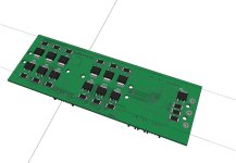
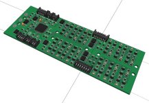
Below are the revised schematics and 3d board assembly. The board layout 3D model is a Sketchup model so can used in mechanical assembly drawings. The board measures 140 by 48 mm, so slightly smaller footprint than a modern smart phone. I wish Eagle PCB could export directly to SolidWorks!

All things being well, it should be up and running by Christmas. PCB is being made now. Software is progressing (time permitting). Let me know if you have any questions or suggestions.

View attachment 3

View attachment 2
Top side.jpg

Bottom side.jpg
 
Pleases me very much to see someone making good use of Walls' design. Would have taken him up on his generousness and sharing had I the skills to build one myself. He's such a polite and helpful fella too. 8)

I always wanted a custom BMS that is designed and built specifically for the Goped ESR... like that one is.... high balancing current and such. I always thought it was such a well thought through design. Anyways I sure am glad to see that someone is taken him up on it for their own application. :D
 
Interesting design.
However, if I understand this right (on my phone now, so small screen, etc.), this BMS has quite high current draw in standby. This might be a serious problem with small (which ebike are) packs.
It pleases my eyes that finally a DIY BMS uses SMD components (and reasonable quality connectors), but its still quite big and has no enclosure :(
 
Hoping to reduce standby current to below 500uA. I guess size is relative, but for the capability it provides it's pretty small, about the size of an iPhone. yes, it doesn't have an enclosure but that's just because it is designed to be built into the frame of my project, so doesn't require a separate enclosure. Adding an enclosure would be pretty straightforward, though.

Yes, I made a point of using decent connectors, yet still conscious of cost. Not a big fan of the ubiquitous JST connectors.

I am in the process of pricing up the bill of materials.
 
Nice work, I like the sketchup model! If you have a link to some instruction to do that let me know, otherwise don’t worry, save your time to get a much better standby current than the 500uA you are targeting, I’m sure you can achieve sub 100uA with even using C :), it’s all about setting the PIC in the right power saving mode.

You should consider having a temperature sensor on-board. I got my BMS really hot a few time during development, so given yours is smaller and higher power, you will have fun with heat dissipation, especially during balancing. You definitely need to implement the adaptive balancing current depending on the number of cell in HVC but that “just” software.

One thing, I never liked too much on my BMS is that the current regulator has a maximum limit and if your power supply happen to go over that even momentarily, the FET will have to dissipate a lot of power and get really hot. This is likely to happen in the “STATE_CHARGE_INIT” when you start the charge and want max current to check if the charge is really going on. For that I would suggest you add a same FET in parallel of the current regulator FET but directly controlled by a GPIO to guaranty saturation during STATE_CHARGE_INIT then only enable the current regulator if the current is less than the max regulator current.
 
I think the main problem with this BMS is that the balancing is uncontrolled. I just can't see a logic in including a relatively fast MCU and using it to only monitor the voltage. It could speed up the balancing drastically.
 
Thanks for all the suggestions. I am not sure I agree with the balancing being "uncontrolled". It may not be directly controlled by the MCU but it does achieve a pretty good state of balance in the cell pack. And, yes, the MCU is definitely over spec'ed, but I have all the debug and development tools for this one, and know it well.

The Sketchup model is a decent stop gap measure in order to get at least a CAD model of the PCB. I wish there was a direct conversion to an industry standard model that SolidWorks can read, such as STEP or IGES. There is apparently a converter from Sketchup to Solidworks but it's not cheap and it's yet another conversion step. Sketchup will have to do for now. More detail on how to use Sketchup with Eagle CAD is here:
http://eagleup.wordpress.com/

Good suggestion about the temperature sensor. I'll see about adding one. And, yes, I was planning on making the balancing software function a bit more "sophisticated". I'd really like to get the balance to near 10mV.

I am in the process to more accurately estimate overall standby current from all the possible strands of consumption. It looks like the individual cell circuit and the voltage regulator contribute at least as much as the MCU.

Good suggestion about the parallel FET and was looking at exactly that a little while ago. However, I fairly certain it will work OK but was going to prototype that circuit and see how it behaves. I am hoping it will work OK as is.
 
What I tried to say by "speed up the balancing" is.. Now, when one cell hits 4.2V, it is already 100% in SOC, so the BMS reduces charging current not to go over that voltage and to charge other cells slowly.
Imagine it working the other way. Let's say one cell outstands from others with slightly higher voltage. This may as well happen anytime during charging... The MCU, seeing that, makes an assumption that this cell will be the first to hit OVC, so it balances it, even if it is only 3.9V or so. While balancing it, MCU does not decrease charging current. What this gives is that all cells are practically already in balance when any of them hit the 4.2V. And so almost no prolonged "balancing" stage with decreased current is needed. We call it "early balancing". It's a well working function of my company's EMUS BMS, which manages to charge 100-200Ah cells with no (or almost no, depending on cell quality) overdue, while balancing at currents as low as 500mA (configurable up to 1.6A).
But anyway I can not see a way you could do this with current hardware.
 
you can always just put a switch in the circuit current to reduce the standby current consumption.

we can do this already with the other 'analog' type BMSs which balance fine and also can be used in bypass mode so that the main discharge current path is not through the BMS.
 
@circuit: There is no doubt that more sophisticated designs for balancing exist (such as yours for example). Having had a quick look at your products' website, this would cost 457 Euros for a 12 cell model. I am hoping my adaption of walls99's design will come in well under a 100 Euros. Or, put another way, there is no way that I could afford a 450 Euro BMS in my project.

It is what it is and I am certain it will work very nicely for my needs. From the outset, I was looking for a BMS that is inexpensive, compact, and has the right set of features. Walls99's design easily meets all of them. His design is by far not the only one I looked at including many commercial ones. This design will not address everyone's needs. Hopefully, some people will find it helpful. I know I did.
 
OK, small update on the standby current consumption. With a couple of small changes, the standby current is just under 200uA. I am OK with that. Also added a couple of on-board temperature sensors for safety as suggested by walls99.

Going to order a couple of board this week on 10 day turn, so hopefully have a first power-up in early December.
 
For anyone still interested, after a few minor changes, the board design has gone to the PCB house (http://www.wedirekt.de). Should have 2 pPCB's back in 2 weeks time. Just in the process of pricing up the BOM and order all the parts.

Here is the 3D model as submitted to the PCB house:
BMS-lipo-12s.jpg

Been thinking about enhancing it further and future revisions. One thing I'd quite like to add is Bluetooth to talk to an Android smart phone. It would be quite handy to display things like:
- State of each cell,i.e. charging, balancing, full
- Charging current
- Pack voltage
- Pack temperature
- Number of LVC/HVC events for each cell to identify weak cells
- Number of charge cycles
- Charging time
- BMS status/errors
- Event log history

All nice things to have and should be able to keep the same footprint. The hardware design doesn't allow for individual cell voltage monitoring, but that's OK for my needs. The MCU has plenty of head room and I/O pins for a Bluetooth module. BUT, first I'll need to get the current version running and some charging cycles on it.
 
Nice!
Yeah I was thinking it would be great to have something that could watch my lipo packs at cell level and send info via Bluetooth to any iOS or Android device that I could watch mounted on the handle bars etc.
Then I started thinking more evil, what if the device also had GPS as well, and what if one of the cell packs was instead of RC lipo was actually C4. That way if some one stole my ebike I could blow them up conveniently from within the iPhone/ipad device app. :mrgreen:
Ok maybe just a little too James Bond, just make an option to over volt the cells so they turn into a fireball.
 
Hurray! PCB's just arrived. Looks just like it should. Now need to populate it and do an incremental bringup test, which I'll hopoefully have time for this weekend.
 
Subscribed! Nice work here! :)

Tommy L sends..... \\m//

heavy-metal-hand-gesture-smiley-emoticon.gif
 
2moto said:
Been thinking about enhancing it further and future revisions. One thing I'd quite like to add is Bluetooth to talk to an Android smart phone.
Hi there.

I must say that at start I was happy to see this message, until I found you aren't sharing the sources/your project is not OpenSource.

I plan to do the same as you describe but in OpenSource way, just like I am doing with Smart EBike Controller: http://smartebike.likesyou.org/
 
2moto said:
Hurray! PCB's just arrived. Looks just like it should. Now need to populate it and do an incremental bringup test, which I'll hopoefully have time for this weekend.

that board is for surface mount parts and reflow or hot gas soldering. nobody here has that kinda capability. why would someone even wanna do this anyway. there are so many useful and effective BMSs out there for far less money. and no soldering of surface mount parts. i doubt if anyone can put one together without shorting out something. this has not a chance in hell of working.
 
walls99 said:
dnmun said:
i doubt if anyone can put one together without shorting out something. this has not a chance in hell of working.
Manually soldering SMD is not significant more difficult than through hole parts. My manually assembled SMD BMS is working fine.

IMG_3541.jpg

dnmun said:
why would someone even wanna do this anyway. there are so many useful and effective BMSs out there for far less money. i doubt if anyone can put one together without shorting out something.
I understand this is problem and that's why I think this projects need to be commercial, so this boards/products can be soldered and tested automatically.

I just bought on Ebay for 44€ an ATTEN-AT858D+ Hot Air SMD Station, right for solder and unsolder components for this projects :)
$T2eC16RHJHIE9nyseGoiBQ3GCtl4q!~~60_3.JPG
 
dnmun said:
that board is for surface mount parts and reflow or hot gas soldering. nobody here has that kinda capability. why would someone even wanna do this anyway. there are so many useful and effective BMSs out there for far less money. and no soldering of surface mount parts. i doubt if anyone can put one together without shorting out something. this has not a chance in hell of working.

Well, I am sorry that you don't have the skills to hand solder a surface mount board. However, other people quite obviously do have such skills. Mine has been complete since early January and is working very well for me. It has now completed about 10 cycles ad balances each cell quite nicely. It works as designed.

Your outlandish predictions are very wide of the mark, indeed.
 
dnmun said:
well let us know if anyone else can do it. why would they when they can buy a regular commercially available BMS for less?
I got a battery pack with problems because BMS were working incorrectly (is damaged) and discharged one cell. The BMS have some LEDs but obviously I don't see the LEDs nor I do have any way to monitor the state of the cells without opening the battery pack. That's why I plan to do my BMS with wireless communications so I can monitor each cell value on my SmartPhone (using Bluetooth) and/or on the Smart Display (using nRF24L01).

OpenSource and DIY plays an important role here :) -- but I also believe is possible to do at the same time a commercial and professional product -- see the big success of Adafruit Industries selling OpenSource hardware: http://www.adafruit.com/
 
dnmun said:
well let us know if anyone else can do it. why would they when they can buy a regular commercially available BMS for less?

Sometimes it is fun to build your own things from scratch, learning and knowing how it works from the inside out. It may be cheaper in the long run because it probably is better than some chinese BMS and is easier to repair and diagnose if something does go wrong with it.
 
ok, then rather than describe it as cheap and easy to assemble why not state how much all the parts will cost plus shipping along with the cost of buying the pcb.

then describe how many hours it takes to assemble the parts in place, then solder.

for the hot gas soldering it requires using special solder with the tiny little bits of solder in the flux, how much is that and how do you place it if not by machine.

like i said, if anyone can solder that thing without shorting it they will be right up there with child slaves in greece who made all the gold jewelry during the hellenic period.

most of these people won't even use a BMS because they feel it is too expensive and even soldering the sense wires is annoying and beyond their interest level.

yes it is a mental exercise for you but i just do not think it is a practical solution for others. but that is jmho.
 
dnmun said:
yes it is a mental exercise for you but i just do not think it is a practical solution for others. but that is jmho.
It is for SURE expensive since is development. I have a lot of expensive lab tools, consumables and electronics components and development boards in stock just to be able to develop my own controller. Also is time consuming. But at least the knowledge is shared and let others improve and give a step ahead.

This BMS (I am mostly refer to the one shared by Walls99) is practical for me, because I am an hacker and I want to make my own and improve/add more functionalities and I don't need to develop and test everything from the start! And in the end, all this can turn in a commercial supported product and then will be "a practical solution for others".

My own company that focus on only one product, started just like this, with me working on the community :) -- and now we are a team of 12 workers in full time.
 
Back
Top