Cell-log LVC "BMS"

Joined
Dec 3, 2011
Messages
196
Location
Alberta, Canada
Hi everyone,

A few weeks ago I was thinking to use the cell-log alarm port to build a sort of BMS. I did several searches on the forum and google but nothing useful came up.
My aim was to use the lvc alarm of the cell-log to stop the load, not directly on a power wire but indirectly, on the throttle or the thin red wire used to "switch on" the controller or the e-brake wire. Basically anything that can stop the discharge of the battery without interfering with any power wires.
This to keep things simple,safe and also cheap.

So, with the help of a friend, I decided to build a little circuit using a mosfet as a switch.
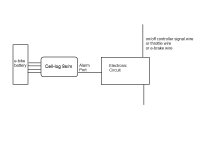
Cell_log_bms.jpg


This is the video of the first prototype. In this case the mosfet is placed on the load just to check if the circuit was working.

[youtube]yF3vf4YXSDI[/youtube]

As you can see from the video the load is cut and then uncut until the battery will stay constantly under the lvc set on the cell-log.
To avoid this I will be building another circuit with a "memory", as soon as the alarm will be triggered the first time, the circuit will open and stay open until a button is pressed and the "memory" is reset.
The new circuit will also allow to connect up to 4 cell-logs and will tolerate a maximum voltage of 120v (cells fully charged,not nominal voltages).

I will keep you posted!
 
Look forward to seeing the actual circuit.
 
go read fechter's thread on hacking the cell logs. at the end, otmar has introduced the use of an opto to drive the alarm circuit and that could be more useful as a circuit to control charging and discharging.
 
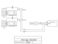
Keep in mind the negative terminal of the alarm output is connected to the bottom cell, so if you are using more than one, it needs to be isolated or you will create a short when connecting them.
The CellLog hacking thread is here: http://endless-sphere.com/forums/viewtopic.php?f=14&t=20142&start=165
On page 12, Otmar's optocoupler mod is shown. If you have optocouplers on the alarm outputs, the optocoupler outputs from any number of CellLogs can be put in parallel and used to pull the throttle down.
The hacking thread doesn't show the external optocoupler setup. That was somewhere else?
Ah, I found a copy in my files:
CellLog Isolator.jpg
 
in the data sheet for the cny74-2h optotransistor the emitter collector voltage has a 7V minimum or is that like a maximum for the transistor to be reverse biased? is this relevant in this application and how does one determine what resistor to use to control the current through the led part of the opto?

you have 10k, about 32V max for the 8S lipo, so that is 3mA of current to drive the led. i noticed that ping uses the everbright 817 optotransistors and he drives them with the seico 6 pin comparator chip on each channel for LVC and for HVC.

he uses 2k for the current limiting resistors, and assuming 2V for the LVC, that is only 1 mA of current to drive the led. does an opto transistor age and lose performance if it is exposed to excess currents or minimal voltages over time? i have wondered if this is why the pings go bad, because the led is on and drawing so much current or so little current that the photo transistor in the 'detector' side is damaged.

looking in the mouser catalog there are 8 pin and larger packages housing more than one opto so a series of optos could be contained in one chip. there are also optos with darlington outputs, triac outputs for Ac, and also solid state relays types using mosfets in the 'detector' or output side where an npn transistor normally is used for an an opto transistor.
 
The CNY74 is only one of many optocouplers that would work. On the emitter side, it takes a minimum of around 1mA to fire. It can run continuously at over 20mA without overheating. You could use a 4.7k resistor instead of a 10k in series with the emitter for higher drive. The emitter will fire when it has about 1v across it, but these are really current operated devices, so 2-5mA is a good range to target. The resistor choice will depend on the voltage (number of cells) used on a CellLog.

On the output side, it's rated for 70v max. When it's on, it will pull down to about 0.3v. Not exactly sure where you're reading the 7v rating from.

I've used other optos on other projects that are very similar. Yes, you can use a dual 8 pin package for two CellLogs. LTV-826 is one I've used before.

To operate the HVC on a charger, there are a few possibilities. Typically you can't share the opto output between a LVC throttle pull down and a HVC charger control due to different ground references. You can use dual optos on each CellLog with the emitters in series and the outputs separated for LVC and HVC. If you're only using them for charging, the the single opto is fine. In the HVC charge control mode, you need to find a way to interface the opto such that it will kill the charger output. There should be a way to use the temp input, but I don't have the charger info to tell exactly how that would hook up.
 
Hi guys,

thank you for the replies and your interesting comments.

My aim is to create a universal board that works up to 120v & 4 cell logs where you just have to plug in the +ve and -ve of the battery pack, the cell log alarm output and connect the wire that you want to connect/disconnect. No need to open the cell-logs unless you want to for your own reasons, the board will be just "plug and play".

I will receive some components in the mail this week and hopefully I will have time to work on a prototype during the weekend.

Eventually I want to add the HVC cutoff directly on the charger DC wire, but let's go one step at a time.

@ Fechter, if I understand correctly, with the schematic you posted the throttle will still be subject to the "hiccup" shown on my video right?

Cheers!

8)
 
if you go read through that thread you can see that the ability to spread the circuit current for the cell log over the entire series of cells in order to keep the cell logs from unbalancing the measured cells is what richard did originally and then otmar hacked it some more with the final result now is that the cell logs can be used to control an optotransistor through the alarm output. the way he has it in that diagram shows what you would do if you had 4 of these connected in series. you have to isolate the alarm output of each section of cell logs as they cascade up in voltage. so this design would work if there were 12 or 15 sets of cell logs, and the output could control a big solid state relay too.

all this together finally swayed me to buy some to hack them up so i bot 3 when i ordered another watt meter from HK. i wanna do these hacks. so cool.

i have a buncha the 817B optos i bot on ebay too if anybody wants some.
 
I designed something like that a while back. Another nice feature is to add a switch to disconnect the cell 0 pin when in standby so you can leave the CellLogs permanently attached. They still drain quite a bit disconnected, like 400uA, but far less than when connected. I found some 4PDT switches that would do 4 CellLogs without resorting to relays, etc.

I didn't watch the video, but when you hit LVC, it will hiccup at first, giving you a warning that's hard to miss. If you keep going, the hiccups get longer until it just won't go anymore.

40S anyone?IMG_0009.JPG

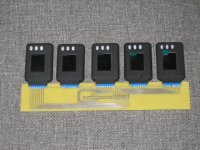
This was for another project, but shows some nice board mounted connectors for the CellLogs. If you plug the balace taps from the cells straight in, you don't need this perhaps.
 
Yeah been there done that, but you still end up unbalanced after long enough - the Cell-Log HVC/LVC board I designed fixes all of these problems, and balances as well.
 
The standby drain problem is why I didn't really go further with CellLogs. heathyoung's circuit takes care of it but takes quite a bit of extra building.

If you disconnect the CellLogs completely when not in use, it works OK, but it's a hassle to constantly plug and unplug them and is inviting failure at the connectors.

I looked at using little relays on the inputs. This actually works out pretty well but the relays are a bit expensive.
 
Hi guys,

I just finished the prototype with the memory,It works pretty well so far. I made a little video as a demonstration.

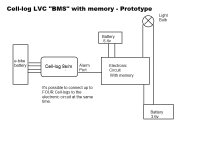
This is how I connected the circuit:

Cell_log_bms 2.jpg

Right now I am using battery and an lm7805 to power up the circuit. In the future (if I will make a PCB) the circuit will be powered directly from the battery pack.

The small light bulb is just to give a visual explanation of what's happening.

The big light bulb is 12v 50w and is used as a load to discharge the battery.


Video:

[youtube]MOYnc-P3Nxg[/youtube]


Next step is to add the HVC function cutting/uncutting the charge directly on the DC wire.


Have a great day everyone!

8)
 
Back
Top