24s BestechPower BMS Thread

sacko

10 kW
Joined
Jul 4, 2012
Messages
840
Location
Kent, United Kingdom
These could be quite popular, so thought I would put some more information up about them.

http://bestechpower.com/888v24spcmbmspcbforli-ionli-polymerbatterypack/PCM-D131.html

You must specify your desired parameters before you order

The unit itself is a lot smaller than I had anticipated, that is an Iphone 4s in the pictures for comparison.


Balance voltage for single cell: 4.20V±0.025V
Not good enough, still need a balancer/balance charger. But it will do nicely for LVC/HVC
 
i am about to order several BMSs from them. i am working on a 15S now and will use the HCX-D126 which is $19. i am also gonna get some others and thought i should post up the prices i got from henry zhang who is the USA sales guy for some of the BMSs i am looking to buy.

http://www.bestekpower.com/555v15spcmbmspcbforli-ionli-polymerbatterypack/


the D126 is the only one designed specifically for 15S, and the D141 is identical and uses some data com output to display the battery parameters on an lcd display or recorded to the pc.

here are some quotes: (you can use their website to see pictures and get the data. they only sell HVC=4.25V and LVC 2.5V and i decided they know more than me so i accepted these setpoints.)

D100 16S $35
D107 20S 39
D132 16S 29
D131 24S (80A=58, 50A=57)
D138 24S 100
D141 15S 35
D126 15S 19

cheap is my favorite number so D126 is for me, but the extra holes along the side where the sense wires connect allow me to parallel more cells and the two hole in the center next to the middle controller IC in that picture are for the thermal breaker so i know i can use that to turn the battery on and off with my little DIP switch

http://www.bestekpower.com/555v15spcmbmspcbforli-ionli-polymerbatterypack/PCM-D126.html
 
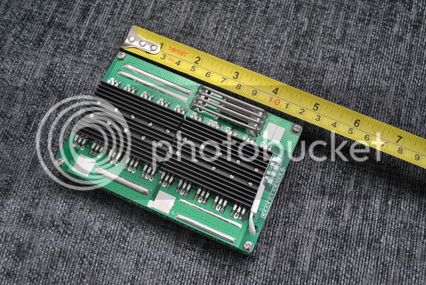
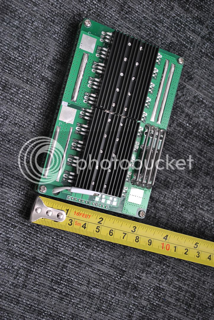
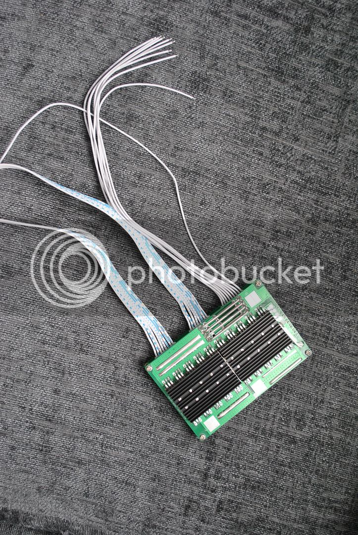
bought one 24s lifepo4 (the very exact same one like in the 1st post except it's not lipo but lifepo4).
had some good conversation with henry, and even tough they didn't send the tracking# as requested it arrived within a week.
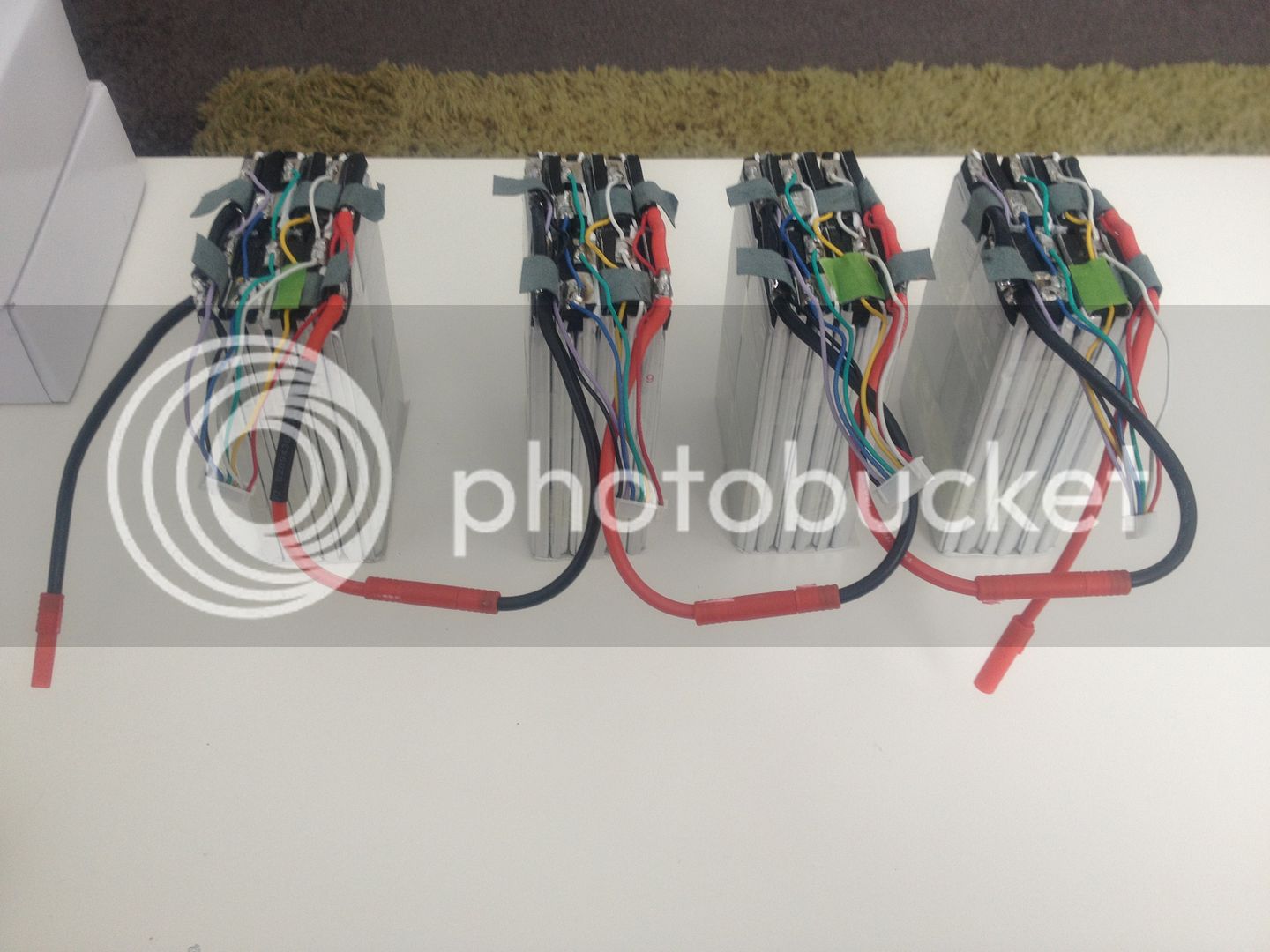
connected it to my battery, and charger and startet charging. no fire, no flash, no bang. that's a good sign ;)
my charger is set to 86.4v end voltage, and starts to lower current afair somewhere near 84v.

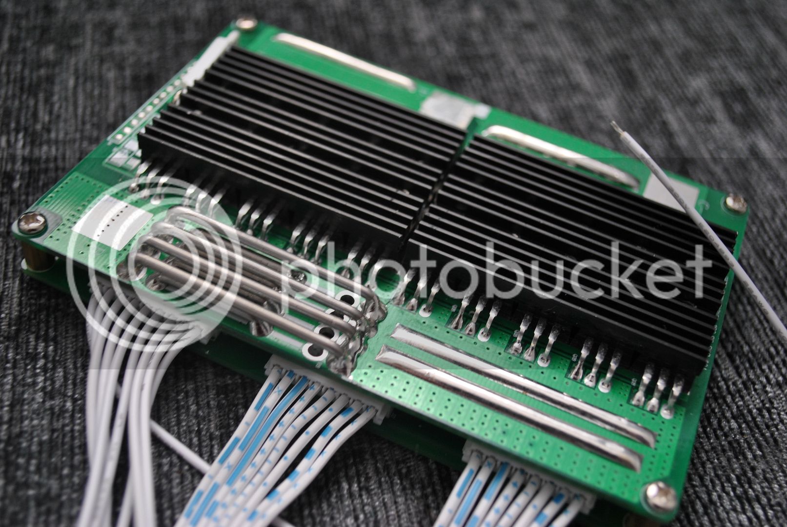
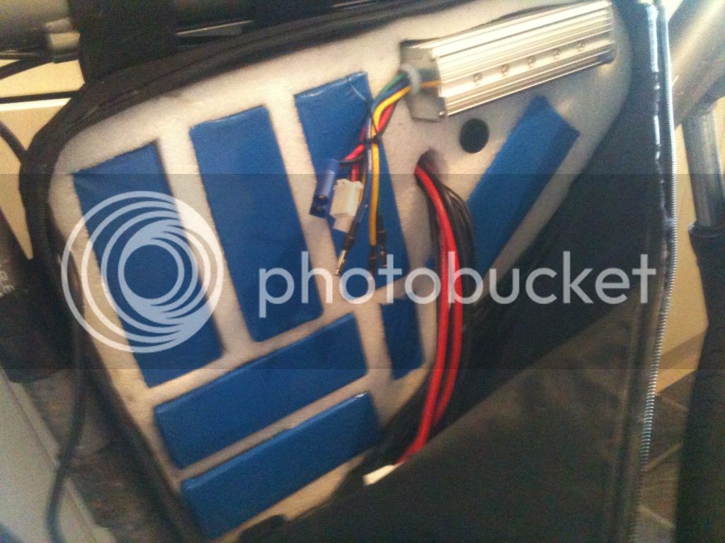
the whole pack is about 50mv out of balance when the first cells reach 3.6v, and the bms is fully balancing at that time. the backside of it (the side w/o heatsink) get's up to almost 100°C. this is REALLY hot, and i'm not sure if i can mount it directly to the any surface as i was planning to do it. of course balancing is not finished when the whole pack reaches 86.4v, and some cells are 3.66v, and some are 3.48v by then.

there is a question left: how can i assure that the pack has enough time to balance?

would i:

a) raise the chargers cut off voltage, so the earlier high cells will get even higher, but as well the low cells. so all cell can go above 3.6v which is the balance voltage set by the bms?
b) lower the charger's voltage at which it starts to lower current, giving the bms more time for balancing before some cells overshoot, and the pack reaches charger's hvc?
c) something different?

thanks!

ps: this is the datasheet and selected lvc/hvc values https://dl.dropboxusercontent.com/u/1174616/24S D131 LiFePO4 BesTech.pdf
 
no, don't change anything now. the reason it is hot is because it was balancing a a lot of current. it has a balancing current about 3 times as large as the ping signalab so the heat is much higher. you wanna have the resistors exposed to the air for sure so they can radiate the heat.

the 15S lipo BMS i ordered has just one 100 ohm resistor so it is only 40mA.

you have 4 of the 100 ohm resistors in parallel so it has an equivalent resistance of 25ohms. at 3.9V the balancing current is 156mA.
 
balance current is quite high. i was wondering how it would handle the heat as i saw the product data.
the question is: as i understand it balancing voltage of 3.6v means that all cells above that value will get pulled down to 3.6v. but what happens to those lower cells that are still below that border voltage even at charging end? they stay there, and will never balance? should the kingpan charger restart charging after some time? or is it off for ever as soon as it once stops? so i would need to start the switch from CC to CV earlier, or should i raise the HVC? because if i don't do anything cells will never get balanced. correct?
 
Subscribed!

I just received my Signalab 16s. Man.....It's tiny!
This is my first BMS and I'm interested in the BestechPower units
as well. Learning about the BMS World now :)

Tommy L sends.....
mosh.gif
 
izeman, the charger shoud go to the final voltage and continue at CV delivering a small balancing current that is used to charge up the low cells. if one cell goes to the HVC then the entire charge is turned off as that cell is drained down to allow the charging to turn back on again. this continues happening until the cells are high enuff that when it cycles back on again after the last of the HVC cutoffs, then no cell can reach the HVC and the charger continues charging at the low balancing current rate so the low cells continue receiving charge and the full cells have the current bypassing them and going through the shunt resistor.
 
Thanks to Dnmun I have got this far, but is this 'drawing' correct?

What happens to the white and red balance wires on the Hobbyking Lipo of pack 4?

2CD19A64-C550-44BE-BEB6-1E873572D6B7-2486-0000020D4C4999EA_zpsc302cfc5.jpg
 
sacko said:
Thanks to Dnmun I have got this far, but is this 'drawing' correct?

What happens to the white and red balance wires on the Hobbyking Lipo of pack 4?

On BMS1 and BMS2 there are 8 pins on each not 7. Rework your diagram and re-post :)

Tommy L sends.....
mosh.gif
 
yep, 8 pins on the two upper connectors but you got the black and red connected correctly.

you will also have to connect the pack in series through the EC5 plugs too. red to black from top of the first pack to the bottom of the next pack all the way up to the top pack.
 
Thanks, are people making a wiring harness to attach their BMS's to the 24s pack, as I presume from looking at the wiring diagram you cannot just solder your main discharge leads to the BMS.

I have attached the BMS Spec sheet and wiring diagram.

2F56A913-A806-49DB-BE15-00C3A2A3C7E3-6102-000003AAFE5A6715_zpsd504e612.jpg
 

Attachments

  • 24S D131 80-20amp.pdf
    160.2 KB · Views: 228
for my lipo build i am gonna cut off the JST plugs, clamp all the cells into one bundle with endplates and wrap some tape around it to hold it solid. then unsolder the big terminal leads and connect the packs in series by soldering a jumper from one to the next and remove those big wires altogether except on each end if i still need them on the battery.

you have to put a piece of insulating plastic across the other side when you connect the individual packs in series because the two terminals are too close and they can short out. then i will just solder the BMS sense wires directly to the individual cells in the full pack.

my lipo and BMS is still in transit so eventually i will get it done.

the leftmost black wire is the main B- lead and that connects to the B- spot on the BMS. the P- spot is where you connect to the controller and C- is where the charger negative attaches to the BMS.
 
Thanks again :)

Mine is staying as it is for now as I'm putting it into a FlaconEV bag. Just awaiting the controller now and I'm good to go.

Something like my previous build.

EAF13D41-FEA2-4C21-98AE-7ED9C62055FE-1215-000000FF948C45EF.jpg
 
you need to have the controller and the BMS out in the air where they can be cooled by the air flowing past them.

i have no use for the lipo in the individual 6S packs since i will assemble the pack into one 15S brick with only the BMS sense wires coming out. i will never use a balancing charger on it. just a bulk charger with the 15S BMS to balance it.
 
dnmun said:
you need to have the controller and the BMS out in the air where they can be cooled by the air flowing past them.
i agree on having the controller outside the bag. but the bms? if you don't isolate it, and it can be touched, there are soldering points easily touchable that carry pack's full voltage. this is too dangerous.
but as i mentioned earlier: balancing resistors get cooking hot. i hope the bms was designed with isolation in mind? all batteries with bms installed come in an isolated pack. i will NOT cover the heat sink, but it will be located in the battery box. some space there, but NO airflow. we'll see how long it survives. ;)
 
jimmyD uses a sheet of plastic above the BMS surface when he built the headway packs with the signalab BMS, and underneath too but there was space for the air to flow around the BMS surface and allow the shunt resistors and the mosfets to cool themselves.

dr Bass uses a big sheet of copper attached onto the end of the BMS and solders the mosfets to it for a heat sink and it is the drain connection for the P- spot.
 
How do the sense wires work, would they make 6x 4S JST-XH "male" connectors? or do they just provide your own wires to solder up? Either of those are fine for myself as i make the JST harnesses by hand, but if one could purchase Methods parallel board and jumpers, then plug that directly into the BMS, that would be legit. Since the BMS doesn't balance perfectly would be able to throw a 2nd jumper into the Methods board and balance with medics/BC168.
 
dnmun said:
izeman, the charger shoud go to the final voltage and continue at CV delivering a small balancing current that is used to charge up the low cells. if one cell goes to the HVC then the entire charge is turned off as that cell is drained down to allow the charging to turn back on again. this continues happening until the cells are high enuff that when it cycles back on again after the last of the HVC cutoffs, then no cell can reach the HVC and the charger continues charging at the low balancing current rate so the low cells continue receiving charge and the full cells have the current bypassing them and going through the shunt resistor.
so let's make an example:
pack charged voltage shall be 3.65v x24 or 87.6v. so i set chargers voltage to that value.
balancing voltage of the bms is 3.6v. and hvc is 3.9v, release voltage is 3.8v.
i now turned down the cv amps quite low, so the charger doesn't turn off too early and charges longer with low amp (0.2-0.4a)@87.6v. this makes some cells go to 3.68v while some are slowly creeping up to 3.58v. IF i'm lucky at charging end all cells are higher than 3.6v and will be bleeded down to that over time. if not, and the pack is too much oob, than some cells will never be bleeded and the pack will never really get balanced.
what is your suggestion? if i raise charger's voltage to eg 88.x volts, and charge long enough with low amps, then all cells will be above 3.6v. the bms will end the charging process anyway if any cells reaches 3.9v - not that i want it to reach any cell this high voltage! but is this the preferred way?
 
ian.mich said:
How do the sense wires work, would they make 6x 4S JST-XH "male" connectors? or do they just provide your own wires to solder up? Either of those are fine for myself as i make the JST harnesses by hand, but if one could purchase Methods parallel board and jumpers, then plug that directly into the BMS, that would be legit. Since the BMS doesn't balance perfectly would be able to throw a 2nd jumper into the Methods board and balance with medics/BC168.
for the 24s there is one 9pin connector and 2x 8pins. making 25 wires (those come with the bms). yesterday when installing it i thought a long time how to connect everything. i already had 4x 6s jst-xh connectors installed. good to connect celllogs for monitoring them or for balance charging with my bc168. i thought of removing those and to only direct wire the bms to the cells. but decided against it.
second idea was to make a wiring harness: 4x male jst-xh on one side and the 3 male plugs to the bms at the other side. decided against it as this would mean: bms or monitor. but not at the same time. as the bms shows no sign of activity (leds, lcd, usb monitor, ...) i need the celllogs for monitoring.
so i wired all wires the bms comes with directly to the cells leaving the jst-xh untouched.
now i can charge and monitor at the same time.
balancing eorks quite nicely. some 'blocks of 6 cells' are within 5mv and some in the low 20s. that's fine.
 
Back
Top