Another DIY transformer tab welder buid

agniusm

1 MW
Joined
Apr 16, 2011
Messages
2,577
Location
Lithuania, Zarasai
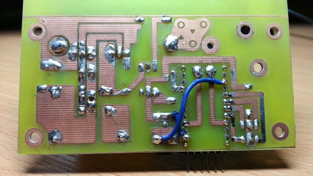
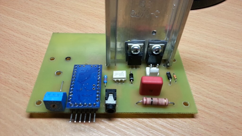
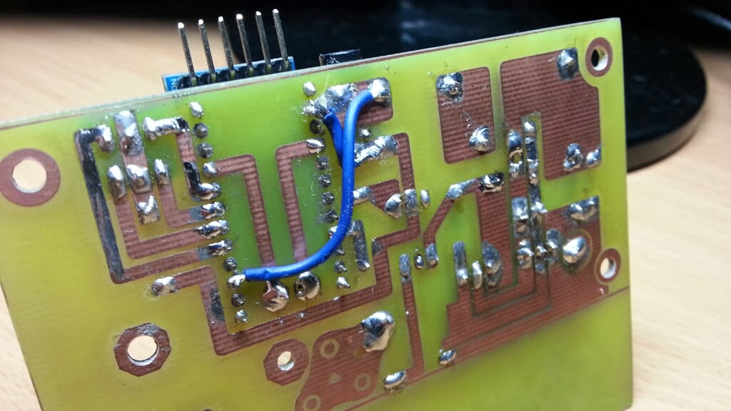
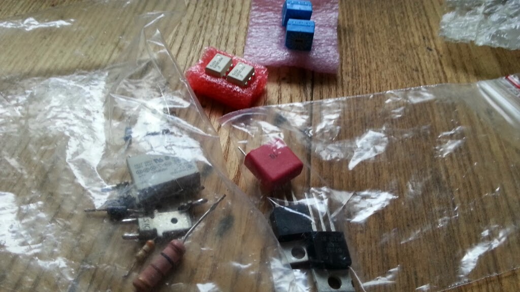
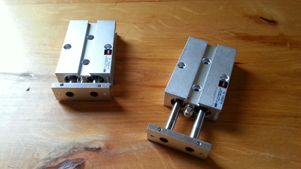
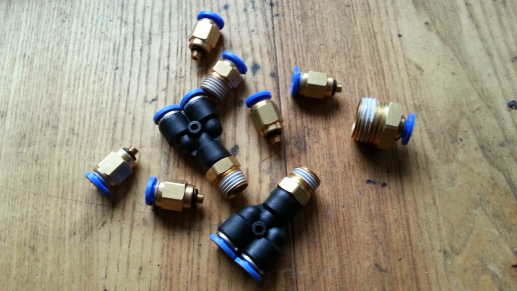
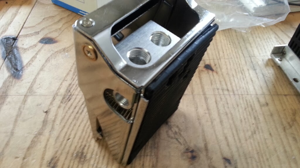
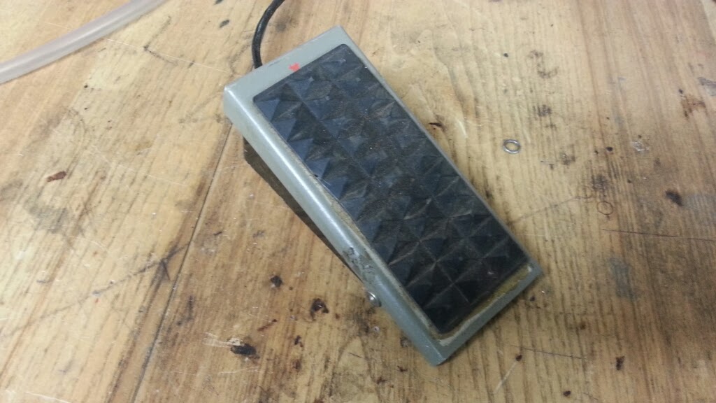
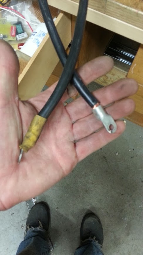
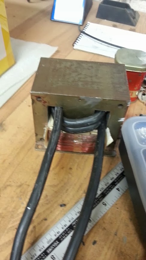
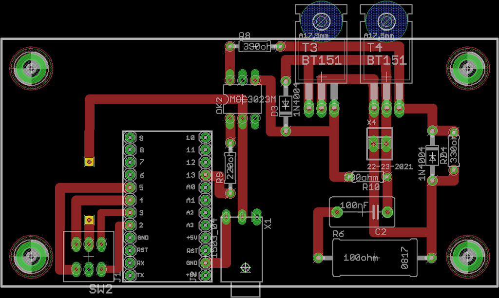
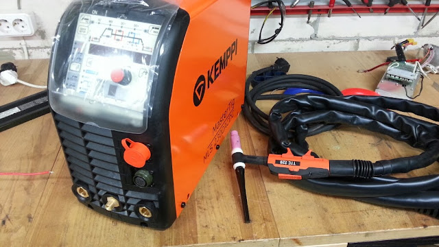
Thought i will start a new thread on this build. Here are the parts i am using:
20140210_123812.jpg

20140210_123824.jpg

20140210_123739.jpg

20140210_120932.jpg

20140210_123555.jpg

20140210_121059.jpg

20140210_192803.jpg

20140212_170625

20140215_120251

20140215_120308

20140215_194737

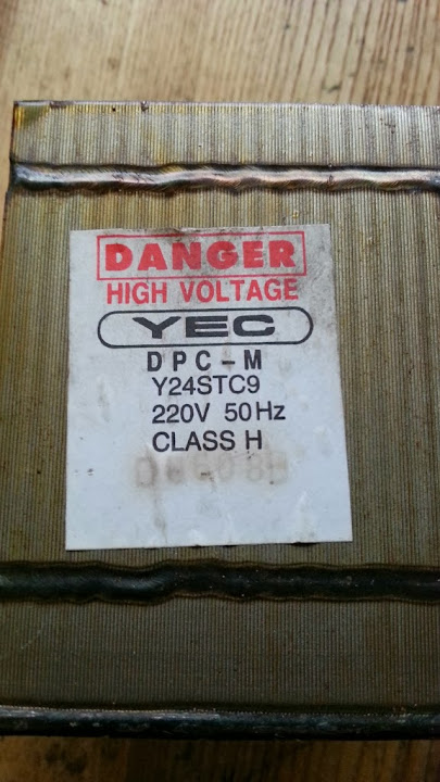
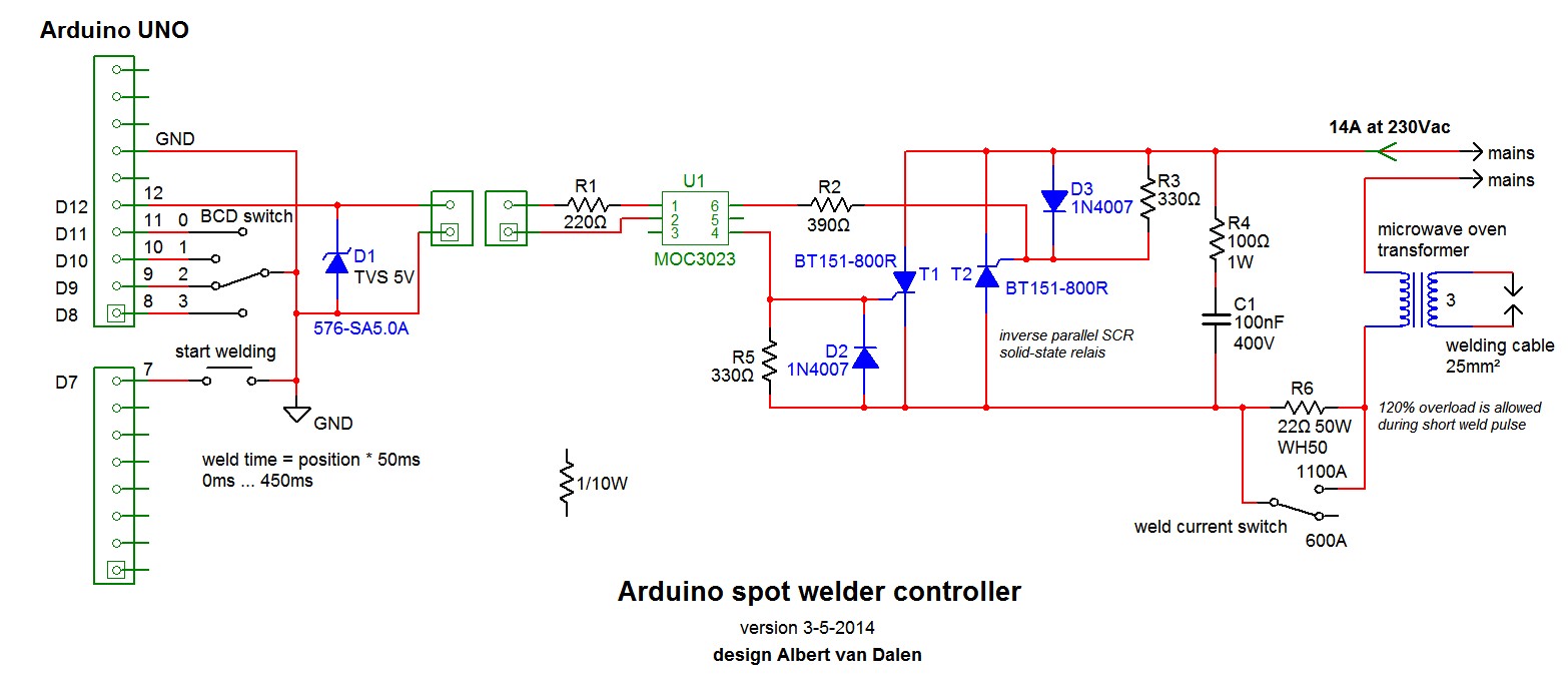
The design is from Albert van Dalen: http://www.avdweb.nl/tech-tips/spot-welder.html
Spot-welder-controller-circuit.jpg

Here is my progress so far:
20140215_172426

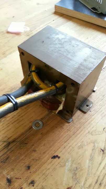
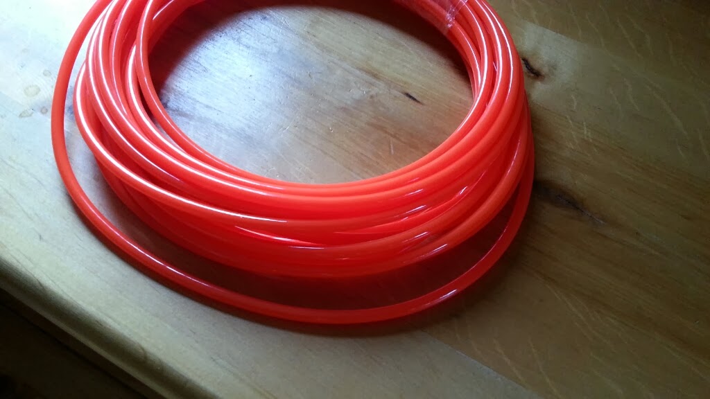
Had to swap coil wire for thinner on to get higher voltage and a bit more flex in cable:
20140215_172435

20140215_172444

20140215_173718

20140215_182550

20140215_195620

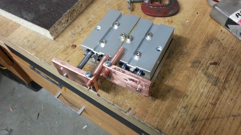
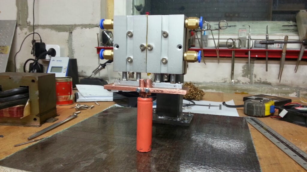
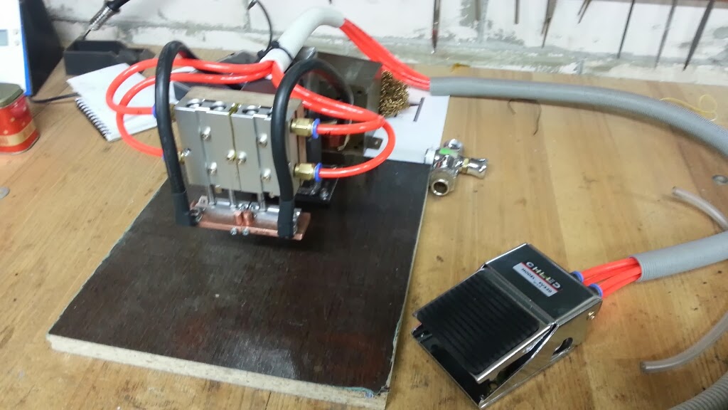
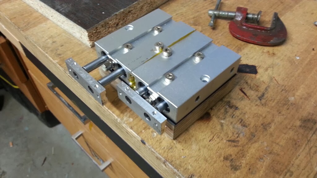
I need to get one cylinder sorted as its jamming. Here is a quick vid on the action:
[youtube]V8P1Z44AtNE[/youtube]
[youtube]5sSYZJCsT9s[/youtube]
 
So I have come to a point where I need to make a PCB. I have newer don this before and am not familiar with eagle or express pcb. If someone knows better software for novice let me know.
You can grab my board files from here:https://drive.google.com/folderview?id=0B56NVZIdTBFOVEpWWkpnOWtLQnc&usp=sharing

My result on attempt looks like this:
Welder.png

I will try laser printer and photo paper transfer method and then just etch it with ferric acid or what ever its called.
I need someone with a knowledge to check my board against the schematics on earlier post. I have used bcd switch part and modified it so it has same pin layout as my bcs rotary switch. It has 6 pins. Middle 2 are common or something like that. I got it of ebay. Here is the link to it: http://www.ebay.com/itm/140916529088?ssPageName=STRK:MEWNX:IT&_trksid=p3984.m1439.l2649
X1 is 3.5mm socket for pedal switch;
X4 is connector to transformer/mains, I probably change it to something beefier.
I am using arduino pro mini and I have swapped some pins on arduino for better routing.
Thanks
 
Recently i have purchased a TIG welder. I wonder if it could be used for cell welding. It has a microtack function on it, it's Kemppi Mastertig AC/DC 2300:
20140115_173202.jpg

Here is a video on microtack:
[youtube]0mFvXvQi4bk[/youtube]
and slowmo:
[youtube]AsUZNXCgBG0[/youtube]
Now if i could figure out a clamp for earth wire i could test it a bit :), perhaps something like this:
tig%2520clamp.png

Any thoughts?
 
Arduino part working:
[youtube]f9px9VdmrD0[/youtube]
Somehow transformer works in reverse, always on, then switches off for pulses
 
So I got this welder working. Arduino part is working fine, probably will atach lcd for to see time setting. Have to worknon pneumatic presure cause it is too high. Also need to reduce electrode travel to 4mm.
Gad some nickel tabs and with 150ms timing it blows through cell with electrolite forcing out. I think this is due high electrode presure and thin tab material, mine was just .08mm. I think 0.25 should fix the issue. Another thing is I got wrong pedal. It does not work both ways so need another one. Here is a quick video of progress:
[youtube]n02m0h_oGho[/youtube]
 
hello,

do you have the software to flash the arduino ?
What about the "zero cross detection" made by d3 in the project by Albert van Dalen ?

Regards
 
Hello,

did you try the kemppi on microtack? I have the same machine, so if this works I would like to try the same thing.

greetings
 
Back
Top