Stepping down high voltage - 150V to 5V

methods

1 GW
Joined
Aug 8, 2008
Messages
5,555
Location
Santa Cruz CA
Spec'ing parts again

I need to step down an arbitrary battery voltage down to 5V.
I need burst power of 60mA or so @ 5V - maybe as little as 30mA but better leave overhead
I need (hopefully) very little average current - converging on 0mA


The linear option (with the obvious limitations)
TL783 4V to 125V, 700mA Linear Regulator
(Can run maybe 7mA @ a 100V drop in a pinch for basically no parts)


Lower Power Switching Option
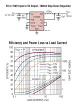
LTC3639 + external components
4V to 150V @ 100mA
You can get about 70% efficiency out of it with an epic drop from 150V to 5V
I imagine cooling will be an issue - have to read the sheets closely
Sleeps at uA's

Higher Power Switching Option
LTC7138 + external components
4V to 140V @ 400mA

Both of the switchers need to run a minimum current to be efficient (yea - seems confusing but true)
You want to size appropriately.

No doubt there are 50 other options on the market.
Really looking for a daughter board with one of these built up already that I can just drop into my circuit - or at least first test on the bench.
I dont have time to let the magic smoke out of every crack-pot over-rated datasheet on the planet :)

Open to options if you have a favorite
You know I prefer Linear Technology... but thats just because they publish enough information to know how well their part will ACTUALLY work once built.

The LT8630 could work
3V to 100V @ 600mA
Lots of low power options there... I like kick-down modes.

I have yet to actually crank the math on these to see how much power I can actually get across my use case.
Not sure what components to spec, what the cost on those will be, where the design intricacies are...

Here is a long list of others.
http://www.linear.com/parametric/Hi...7,1107,1367,2198,1033,1032!s_1033,1!gtd_!t2_0

As always I want to encourage as much "System on a Chip" as possible... so I will accept a less efficient design if it means fewer external components.
Perhaps I can make the little puck that I desire. Going to have to happen... if I want to support packs over 60V.

Actual Customers use points:
Me @ 4S, 12S, 14S, 28S

One switch, any pack.

-methods
 
Methods,

why not using a regular 100-240VAC to 5Vdc adaptor or cellphone charger?.. many times these can take DC at the input as low as 40V dc and can take also up tp 300Vdc too.
:wink:

cellphone 1A charger are VERY compact and cheap! even less than 1 cubic inch with the plastic casing!


Doc
 
This looks so sexy and simple...
It cant be true


SoooSimPO.jpg


-methods
 
I am certainly no expert, feel free to ignore. I would suggest exploring the options that provide XXX volts down to 12V. This provides a wide array of choices for lights, GPS, phone chargers, and music.

A 12V-to-5V device could be added that would be very small, available, and affordable.
 
Ok...

Cin Selection
Cout Selection
Inductor value, size, and core Selection

Total Noob at this... reading the data sheet....

Systems Engineering

Its all about managing 40 different things all of which require extreme attention to detail
Super easy to just focus in on one thing... like BMS chip selection
Focusing in on all those things without dropping the ball is tough.


-methods
 
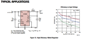
So... lets play it safe and start with a typical application:

TypicalApp.png

This wont be the best
Not the most efficient
Not the least ripple
Not the fastest to recover

But it will work... and there are some part numbers to pick through.

We will use those to run through the calculation exercises that they post.

-methods
 
Input cap
250V 1uF
$1.43
http://www.mouser.com/Search/Refine.aspx?Keyword=810-C5750X7R2E105K

Output cap
10V 10uF
$0.39
http://www.mouser.com/ProductDetail/TDK/C3216X7R1C106M160AC/?qs=LcTL/5vFEzHmDUPbB3OzqQ==

Inductor
1mH 340mA
$1.60
http://www.mouser.com/ProductDetail/TDK/SLF12555T-102MR34-PF/?qs=g8DL0B6GkTlprquS2TaDEw==

Uh... now that was not so hard right?

The actual part is $5
http://www.linear.com/purchase/LTC3639
(lots of flavors tho... need to look into that. I want the best heat sink variety)

And... now to reverse engineer the $200 demo board for ideas:

progress...

-methods
 
I love those doc.
Done it many times - tho never measured efficiency.

My experience has been that they work great for greater than 50V inputs.
I am looking for a solution that will work from 2S up to 30S ... all the same.
Do you have a suggestion that may work to a voltage as low as 12S?
I can manually regulate 4s... but 12S... 14S... these are very close to the threshold and I believe at 30V they show significant output reduction.

Open to ideas as always.

-methods


Doctorbass said:
Methods,

why not using a regular 100-240VAC to 5Vdc adaptor or cellphone charger?.. ----
Doc
 
I hear that for sure.

One of my paths forward requires about 180mA for a 1.2KV 50A contactor
I like settling on a 12V option - then regulating down to 5V where needed.

Sounds like you are talking about having some overhead in there... maybe an amp or two
That could be interesting.

I think first I need to make sure that I can span the entire range of packs - from 4V up to 150V... then maybe if folks want accessory options I can add a nugget like the one Doc suggested.

This particular application - I am hoping to build into a component - and maintain super wide range with good reliable performance.

-methods

spinningmagnets said:
I am certainly no expert, feel free to ignore. I would suggest exploring the options that provide XXX volts down to 12V. This provides a wide array of choices for lights, GPS, phone chargers, and music.

A 12V-to-5V device could be added that would be very small, available, and affordable.
 
methods said:
Spec'ing parts again

I need to step down an arbitrary battery voltage down to 5V.

USB wall charger?

Peak voltage of 120VAC is about 170V.
 
Ok - on Doc's suggestion I am going to do the following:

1) Drag in the 60V 18A Sorensen DCS lab supply
2) Nab Kimberlies APple USB charger :twisted:
3) Cut a USB cable and wire up a set of loads. 5V/5ohms for 1A, 10ohms for 1/2 amp, 25ohms for 200mA (er... my power resistors are over at Calfee's... dude.. F%$K having your stuff in two spots!)
4) Apply a 100mA load and start dropping the supply voltage till it fails

We can calculate efficiency by the lab supply readout vs fluke measured output.

I was once told at the lab:

The difference between an Experiment and a Test is that with a Test you have expectations about results... and with an experiment you just dont know.
I am pretty sure this is a test which will result in non-op below 30V
My requirement is definitely to run 30V and below - so I suspect I can eliminate this as a path forward.

-methods
 
Thanks Chalo
Totally agree. Its the slam dunk, get it done tonight, cheap and easy path forward.

I have tested them at higher voltages but I fear they do not work down to low voltages.

-methods


Chalo said:
methods said:
Spec'ing parts again

I need to step down an arbitrary battery voltage down to 5V.

USB wall charger?

Peak voltage of 120VAC is about 170V.
 
So - I did the math on the down selected components.

It looks like I will be running about 50khz
This is on the low end of recommendations. I am fine with that... tho I will buy variants of the inductor and capacitors when I shop :idea:
(spend the extra $30 - dont be a cheap-ass... you will use the parts)

High Level:

My (admittedly naive) understanding of switching goes as follows:

Big, pig, slow... equates to simple and reliable and unfussy... at the cost of big parts, expensive parts, and of course efficiency.

If you want to start sussing out 5% eff here or 10% there... the cost comes in the form of complexity.
When your inductance values start to get smaller (parts get smaller and cheaper) but parasitics become much more relevant

I selected a 1mH (1000uH) inductor. Thats pretty giant... and so my layout will not be very sensitive to a few uH here and there.
On the other hand... if I select a 200uH..... or a 100uH... now that add-up of parasitics... 1uH here, 3uH there... become relavant
We want an order of magnitude (AT LEAST) between the components we are using and the parasitics on the board.

Same is true with caps... but going Hog-Big can cost you in other ways.
If I dangle 1mF of low ESR off the output... my ramp time will get longer and I may run into brown-out issues with my uController... or just poor settling time
As for the input... I will no doubt put a monster on there... and the cost of that is just spark at connection. No reason to ever under-size input capacitance.

Down stream from my switcher I will no doubt have large caps - but there will be some distance between them (inductance) and I think it will be fine. I think the switcher will slam online then power up my Arduino then clear Brown-Out-Lockup, then GO.

High level.
Please don't knit pick - I usually operate at a higher level (i.e. I usually just grab components and compile them into higher level systems... which is where all things are converging)

And on that note: Every auto manufacturer on the planet should be USING THE EXACT SAME PARTS.
There is no excuse for incompatibility of parts between vehicles. It is pure stupid.
The only argument I have ever heard that is semi-valid (besides the Union argument :roll:) revolves around across the board failures and military / high reliability applications / spreading risk.

This is how things work.
The older you get, the more obvious it becomes.

Capitalism...

Now - to apply this circuit to my "smart switch" design
Decide if I want to make a "new arduino" or if I want to daughter-board it
Calculate my power and make sure it will work
Most importantly... determine how I will easily heat sink the logic gate mosfets... or perhaps go with an IGBT or something else.

Have... uh... I set a target price yet???
Who cares. Build it and they will come.

-methods
 
Now... this is a non-isolated step down.

The project this is going into depended on having an isolated supply.
Originally it was an internal battery...

I can now add a 5V - 5V 1W isolated DC-DC (expensive and inefficient)
Or... sigh... redesign my mosfet output stage.

My trouble is that I want to run bi-directional N-Channels.
Probably just need to suck it up and grab a driver chip.

Isolated is nice tho...
Isolated to a couple KV... with a lot of TVS diodes... avoids a lot of problems.

I will look up and share the isolators I have used in the past - see where they are at these days.


-methods
 
ISOLATION:

I have not used this particular brand. 5V 200mA
http://www.mouser.com/ProductDetail...3zeNPGzHalfJ4U5UAJFUOyEWvY9_68wppoaAsla8P8HAQ

I have used the crap out of this brand
https://www.digikey.com/product-det...Ohyjdkt8g9nguNFzaHcYUoRPWI8RViEbPgaApF88P8HAQ

Simple as it gets.
Upward of 80% if loaded down... not so hot with small loads
Claims 20mA minimum draw to meet requirements. Can be shunt-loaded... but that is savage. IIRC they work fine with 10mA or so of load. Just dont meet spec.

There is a price to pay for the ease of Isolation. Price has got to be paid someplace... either at the coil of a contactor... or at the loss stackup of switchers... or in some other clever componentry.

-methods
 
I want this in 150V......
http://www.linear.com/product/LTC4365

I remember trudging through this a couple few years ago.
Things are better... but it is so hard waiting for technology to evolve.

I need to drive a couple of N-Channels from a ground referenced micro - so I need to high side them... but

I guess I could ghetto-lowside them :D
IIRC you can bias them via the body diodes.
Vulnerable to noise
Sketch probably... need to test

-methods
 
Went around the design loopty loop on cost benefit for Isolated vs non-isolated control of the switch around high side and low side switching options.
Determined isolated path adds too many failure modes in the big picture of requirements

Backed off requirements and recompiled

BMS now lives on the same board as the smart switch
4S - 30S fully populated
0A - 80A mosfet bidirectional discharge control
Optional contactor for currents over 80A continuous - just plugs in
Boot strapped precharge on both, with PWM precharge on mosfet only
IP67 grease packed connectors with a potted assembly
Balance Harness adapters for specific packs (try to keep it to three standards)
Fully programmable via PC or Android via BlueTooth or USB
CAN port with CANOPEN (unimplemented but user programmable)
6 temp probes on the battery, 1 on the mosfet bank
Even cell draw on a 3 second heartbeat should draw next to nothing
Programmable deadman settings, LVC hysterysis, HVC hyst, overall hyst on voltage or time
Guaranteed no connect till output matches input
Replaces all power switches in system with a single starter key or bootstrap button
Fused at 2A if used with a contactor, 100A if used with mosfets. External 300A blade fuse for Contactor option
Balances at >400mA to some temperature, then backs off to 100mA
Very close to completion - at 80%

Have not solved Mosfet mounting and heat sinking
Have not solved IP67 balance tap input connector choice
Have not solved non-pop options (to save $30/unit) if potted
Have not solved isolation issue for programming (may drop USB flavor and say Bluetooth only)
Have not solved voltages over 150V (and not going to)
Have not fully evaluated seamless car battery replacement
Have not fully solved ebike 10S to 24S arrangement
Have not fully solved Zero brick or monolith replacement scheme
Have not calculated full stack quiescent current after power saving schemes enabled - its low

Have solved guaranteed no over discharge, no over charge
Have solved guaranteed no overheat if battery or switch on charge or discharge
Have solved reverse polarity connection and short circuit protection
Have solved precharge and no-connect-till-match
Have decided to share source code... in hopes that a user will implement CAN Open for it.
Have decided to go monolithic. Option to buy switch only. No option to buy BMS only.

...

Solving for the general solution to 3 problems I have a lot of experience with over the last 10 years
*16V 1000A Car Starter Battery replacement (also covers any 12V application)
* 36V to 100V+ Ebike Battery total system management
* 116V Motorcycle batteries

Not competing with the $4 - $140 Chinese "all in one boards
Not competing with any low cost solution that solves for 1 of 3
Not competing in any sort of market race... this one will be the one.... F*&King done waiting for someone else to solve it :?

Solving it my way... very similar to BMS V2.0... but with input and output control, IP67 weathering, better power draw, and a much smaller package

-methods
 
System interface will be at the balance taps, thermal probes, User Switch, and main contacts

Assumed battery has a PCB on it with self resetting fuses with a balance tap/temp connector set of some sort.
For systems with distributed batteries... they will have to shuttle the balance cables, temp wires, and power lugs to a single point.
For paralleled batteries they will need to be "built parallel" - there will be no support for hot-swap paralleling at this point.... I dont think.

The Zero dirt bikes implemented this hot swapping. To me... it adds more complexity than is needed.
It is driven by the human lift requirements... as it would be a single monolithic battery if it were possible.
If someone wants to implement the CAN section then hot swap will be enabled. I am not doing it - CAN makes my head pound due to prior work.

-methods
 
Now... to undo my design dependencies that were first solved by using an onboard isolated coin cell... then were solved by using an isolated 4V to 150V DC-DC...
Now backing off to a single point ground referenced high side switching topology using nChannel fets.

Or low side... but it has to be bi-directional
The Charge and discharge ports shall be one and the same.

And... when this route takes... I can leave taps in for a Hall sensor current monitor or traditional high current or low current shunt.

Dropping USB, UART, I2C support - only bluetooth and CAN - will see if BlueTooth can even handle the noise.

Have one paying seed. Have a prospective seed (his requirements not yet shown).

Will sell them out of Jozztek in the UK and at the same price here in the US out of my garage.
They will be "not cheap" ... but not expensive

One size fits all. We want you to buy 3 of them. They will not blow up or fail.
No expense spared on noise filtering and retard proofing... except at the balance tap connections... where if you fail, you fail.

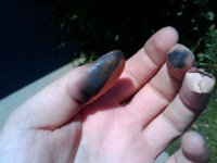
Let me tell you about wiring a BMS into a bike at the race track around 2008... for the first time... an hour before the race started.
No room for mistakes at the battery assembly level. Professionals only. Tinker'ers get Kentucky fried fingers and blown parts.

No nOoBs

Fried.jpg

-methods
 
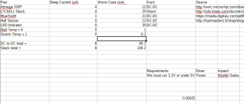
Power stackup is starting to look like this:


Qpower.png

Which boils down to about a 10uA burn (if I implement only Sleep and not a true Dead Man or latching relay)
Peak draw (not including balance) of 100mA - with 86 of that coming off of our 100mA DC-DC

Considering that it is not a complete list... I may need to bump up to a larger DC-DC
Or... Eliminate some options...

Probably bump up to a bigger DC-DC

Off the cuff calculation:
Running for 1mS once every 3 seconds except while communicating?
Thats about a 35uA average draw off the battery for full functionality
This assumes running pig-power on a lot of stuff - full LED output, full speed Bluetooth, 5V CPU...
So - If I try I can get the average current to match the sleep current (almost).

We are running only 333uSeconds out of every second... so thats not a third... its a milliThird (new word)

-methods
 
microwatts controlling kilowatts

When I graduated in 1995 this was not possible
When I graduated in 2001 this was barely possible... but only with infinite clever... undoable
When I graduated tin 2008 this was becoming mainstream

Why?
Thank the Cell Phone ... the primary driver... the mobile ultra high power yet ultra low power
What an art.

Love what it has done to the industry... EXCEPT THE GOD DAMN TINY 0.5MIL PITCH PARTS
Can... we.... not still offer something in Human Size for prototyping ?!?!?!

Imagine how much engineering time we waste fiddling with tiny chips. :!:

Someone could make a business out of adapter-boarding for manufacturers.
Every chip on the line gets 100pcs or 1000pcs or 1Mpcs mounted to a DIP adapter board.

Yes... we still use DIP in prototype... WHEN WE HAVE TO.
SOT is plenty fine.
TSSOP and smaller makes me grind my teeth with wasted time.

-methods
 
Sweet.

Thanks for your help along the way.
I agree that the tiny regulators should end up as a daughter board, potted, and made available...
Tho I suspect many would want more current.

Reference the LTC sample board with jumpers for select.
They are going for $200... we could do them in tiny for $20

-methods


Alan B said:
Excellent and useful thread.

Would be nice to have some small regulator boards for 100-150V to 5/12. Much smaller than AC wallwarts, and much lower idle current.
 
It's not high enough voltage, but is this part useful?
https://www.maximintegrated.com/en/products/power/switching-regulators/MAX17506.html
 
Back
Top