Hillhater
100 TW
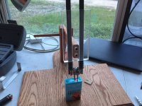
this seems to work ..  :lol:
:lol:
[youtube]UU7QC5Uby6M[/youtube]
:lol:..good enough for the girls i go out with !
[youtube]UU7QC5Uby6M[/youtube]
:lol:..good enough for the girls i go out with !
")
....try the " Mk II"......skeetab5780 said:How would you do the anode of the cell?
skeetab5780 said:How would you do the anode of the cell?
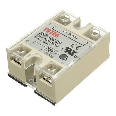
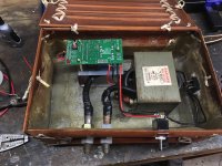
Visual learning anyone?IRF1405 power mosfet's
MOSFET, N, 55V, 169A, TO-220
Transistor Polarity:N Channel
Continuous Drain Current Id:169A
Drain Source Voltage Vds:55V
On Resistance Rds(on):5.3mohm
Rds(on) Test Voltage Vgs:10V
Alan B said:.....Are people really feeling that's too complicated? Or are they just unaware how simple they can be??
remember Alan,..some of the posters on here have trouble figuring out how to solder !Alan B said:.....Are people really feeling that's too complicated? .....??
Alan B said:The code is published, the tools are free. It is about as simple as loading some software, plugging in a USB cable, selecting a file and clicking the "download" button. Remember, Arduino was designed by and for Artists, not techies.