Measuring Vruzend kit resistance?

optimistx

10 mW
Joined
May 9, 2010
Messages
20
Location
Finland
How much do the Vruzend kit "caps" add to the internal resistance of each cell?

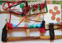
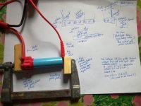
With 2 Vruzend caps around one 18650 cell and their nickel strips in place I first measured with a voltmeter the resistance between the outer holes of the nickel strips, one probe at plus, another probe at minus. The voltage was 4.11 V.

Then I connected a bicycle lamp (6V, 2.4 W) to the cell. The lamp lit, and the amperage was 0.30 A

With the lamp lit the voltage was 4.05 V. The sagging was 4.11V-4.05V = 60 millivolts. From Ohms law R= U/I = 60mV/0.3 A= 200 milliohms.

----

How much of this 200 milliohms is inside the cell and how much caused by the Vruzend parts? Would it be reasonable to improve Vruzend parts, how much could we gain?

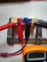
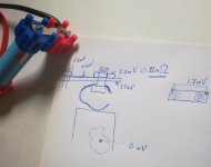
I kept the above circuit with the lamp. I tried to measure resistance with 4-wire resistance measurement : https://en.wikipedia.org/wiki/Four-terminal_sensing
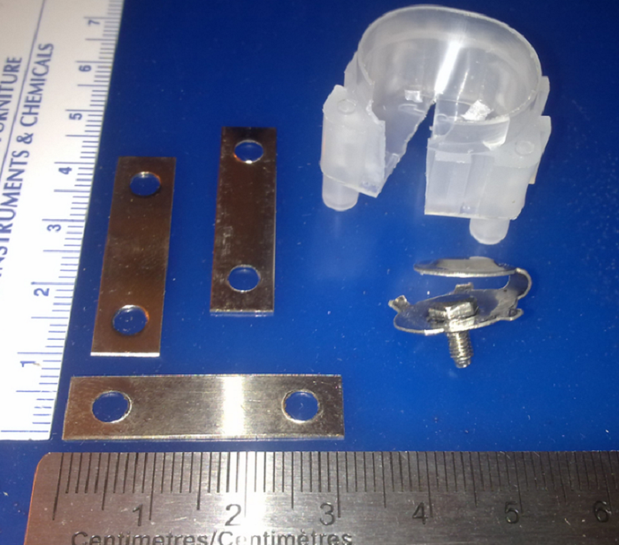
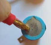
From another cell I removed insulation from a 1 cm2 spot on the side of the cell. It is known to be negative terminal(!). The positive terminal is empty and not used at all. To the negative end I put the Vruzend part, with nickel strip. Then the 0.3 ampere current was arranged through the bare side spot, Vruzend, through the nickel strip.

With voltmeter probes at the bare side spot and the outer hole of the nickel strip gave 8.8 millivolts. Again from Ohms law we get resistance R = 8.8 mV/0.30 A = 30 mOhm.

Hmm, not very bad, or is it? Or is there an important error somewhere here? (the temperature is ignored here).
--------------

When there are 2 Vruzend parts per cell they have together about 60 milliohms and the true cell direct current internal resistance is
Edit oct 12: internal resistance is milliOhms, not milliVolts 200 mOhm - 2*30 mOhm = 140 mOhm.

But here is major error in my thoughts: heat loss is depending of the configuration (Serial/parallel connections). 45W is lost in ONE cell, but of course such currents are not possible in one cell. Ignore the following black lines, I'll write about a new post later today. :oops:
Ok, now the correction: Total_Power_to_heat =( I_total_to_ESC ² / N_parallel)*N_serial*R. Eg. (15A*15A/10) * 10 * 0.2Ohm = 45W ,for 10S10P


My ESC takes at most 15 A, and the Voltage is 36V (40V to calculate easier). At max power heat in the cells and Vruzend parts is I²*R = 15A*15A* 0.2 Ohm = 45 W. The total power P = U*I = 40V*15A = 600 W. The percentage to heat is 45/600 = 7.5 %

Of those 45 watts Vruzend's share is 60mOhm/200 milliohm = 13.5 W. For me this would be tolerable so far compared to the pedalling effort. However, 45 W in a small volume would mean overheating, probably (?), so the average power should be less.

Has somebody else test results?

Thoughts, corrections, remarks?
 
I believe it's possible to overlay the Vruzend end cap connectors with copper foil, and have the result be safe and reliable. If you want to experiment with this, I recommend starting your experiments with 0.25mm thick copper (10-mil, or 30-ga). As far as current-carrying capabilities go, any copper foil that is thinner than this is very fragile, and anything thicker than 0.25mm is hard to cut with scissors (plus, any added thickness over this is probably un-necessary).

If you are using a 7mm wide strip as a bus, 0.25mm thick has the same copper cross-section as 15-ga copper wire. If using one 15-ga wire per cell to accomplish the series connnections, a 15-ga wire can easily handle 15A occasional peak.

https://endless-sphere.com/forums/viewtopic.php?f=14&t=84680&start=125#p1303321
BPBK10.png
 
I made a different arrangement to find out the resistance of Vruzend parts. I put the parts against each other without the cell. It was necessary to break the plastic to make contact with round parts (the part makes normally contact with the cell terminal, now with each other.)

4-wire measurement again.

The image has the parts, crocodile clips carry the 0.3 A current, and voltmeter probes show a value 99.0 mV.

What??? 99.0 mV/0.3A = 330 mOhm!

When the voltage measurement is taken in several other locations inside the Vruzend parts, the huge value is between the contacts (visible in the middle, round parts resting against each other with unknown force). Other intervals excluding the contac give typically few milliohms, e.g. the nickel strip has 3 mOhm resistance between the holes.
This result sounds inconsistent with the previous. The contact surfaces were cleaned with CRC. What are cell materials, Vruzend materials and what do we know about contact resistances between them, in theory?
The ideas to use copper etc are interesting. At first I would try to calculate, how much could be achieved with them, in the best case. 13.5 watts at peak load to waste heat from Vruzend parts is not much for me now. But the calculation might be wrong.
 

Attachments

  • broken_vruzend_contact.jpg
    broken_vruzend_contact.jpg
    28.5 KB · Views: 1,556
One more experiment, the third.

This time I filed the end of the cell, which had remains of previous spot welding. The cell had been removed from a commercial bicycle bottle battery.
I sprayed CRC to all surfaces. I tightened the nut as hard as I dared(not to damage the threads).
0.3 ampere current was flowing from the cell through a lamp.
4-wire measument.

The measurement values were quite steady, and repeated probings gave almost the same results every time.

The results are written to the image.

The resistance from the cell side spot to the middle of the nickel strip, 4.4 mV/0.3 A = 15mOhm, could be used to estimate the resistances between serial and parallel connections. With 2 ends of the cell the resistance is double, 30 mOhms. If the serial connection consists of 10 cells in series, the sum is 10 *30 mOhms = 300 mOhms.

So this test gave better values than the first, only about half of it.

If the resistance would not become worse as oxidation, dirt, etc gather in the contact, this would be so good for me that searching lower values is not worth it.

But it came out that the results can vary a lot, largest values can be 10 times as much as the lowest, depending of many things: cleaning of surfaces, contact pressures, contact surface areas etc.

The 4-wire measurement came out to be easier to use than I ever thought, and very instructive. The flow of the current and the measured potentials (voltages) started to resemble a more or less rapidly flowing river with rapids, waterfalls , calm bays, where I would measure the vertical height differences (=voltages). E.g. it took me a while to understand why the location of the bare spot on cell side has no influence for the result ! (first I thought that the spot has to be very near the middle of the cell bottom so that the resistance of the (unknown) cell cover metal enclosure does not influence the results). But the cell negative terminal is "a calm bay" , branching from the river.... In the same way the ends of the nickel strips were "bays" with no current at all. Fascinating!
 

Attachments

  • vruzend_test3.jpg
    vruzend_test3.jpg
    35.4 KB · Views: 1,501
The Vruzend cap for the cell has 4 hops from one material or part to another:
1. from cell to the "springy" part,
2. then to bolt,
3. then to nut
4. then to nickel strip
None of these hops have solder in them.

From previous image came the idea to try gold connector towards the cell, only one hop. How much voltage diffrerence and resistance would be there?

As in the image below I found a gold plated banana plug to test. The voltage probes were one towards the cell and one towards the banana plug. The current was 0.30 A
The pressure with the finger was not very hard. Only 0.5 mV and 1.7 milliOhm!

What about the nickel strip towards the cell end?

The results were varying depending on the location and pressure. The lowest result was 2.0 mV, 7 milliOhm.

If the gold plated part against the cell really has so small contact resistance, why not use that?
 

Attachments

  • vruzend_gold.jpg
    vruzend_gold.jpg
    6.1 KB · Views: 1,473
The resistance between the gold plated banana contact and the cell negative terminal is even less than in the previous image, when moderate pressure is applied.

The voltage is so small that my simple multimeter might be unreliable, about 0.05 millivolts perhaps. The numbers fluctuate between 00.0 and 00.1 millivolts and therefore I guess 00.05 mV. Current is 0.30 A, so 00.05 would mean about 0.2 milliOhms. Too good to be true?
If the goldplated piece of something makes wonders, why not proceed to playing wtih crazy ideas? Flashlights have cells in a tube, probably touching each other without anything in between. What if there is "something goldplated" but nothing else? (my cells are flat top and do not conduct reliably in a tube).

Put say 5 cells serially (into a tube or) into a track made to a piece of plywood (= bottom of a plywood box). "A piece of something goldplated" (corresponding to the banana connector )is put between cells. As a bonus the golden piece works also as the connector for one thin balancing wire.

The 5 cells can be clamped between the ends of the plywood box (the length about 40 cm), with possibly bicycle tire stuffing to give some spring action (?). When clamping, the cells must be kept straight Therefoer the track, and some method to keep cells down).

This may have been already tried, but I did not succeed in googling , lack of good keywords.
 

Attachments

  • vruzend_gold2.jpg
    vruzend_gold2.jpg
    35 KB · Views: 1,446
In the absence of a separate copper foil overlay, I would like to suggest a copper-plating applied to the stock contact as an alternative to gold.
 
spinningmagnets said:
In the absence of a separate copper foil overlay, I would like to suggest a copper-plating applied to the stock contact as an alternative to gold.
Exciting idea! I made a resistance test with an European Union 5 cent coin in the negative terminal. Result: Perhaps even smaller resistance than the gold plated banana connector, because multimeter showed steadily zero millivolts, 00.0 mV (less than 0.05 mVl I guess). Remains to think and test how to guarantee as good contact with the positive terminal. If this works, we make a battery with money, but we do not make money ;)
 
Serial setup with 2 cells:

There are 10 copper plated coins between cells instead of one in order to measure the resistance more accurately.
The rightmost coin has very thin balance wire soldered in the middle (too ugly soldering with 30 Watt device).
There are coins in the alligater clips also, else my imaxb6 refuses to balance. Now it discharges and charges.

The resistance in one hop between coins is 0.17 milliohms . The pressure in the clamp is very small, only to keep the parts lined.

Also in the hop between the cell negative terminal and the coin the resistance is about 0.1 milliohms (the accuracy of the multimeter is limited here).

A hop from the coin with the soldered spot in the middle seems to have a little more resistance. Difficult to be sure.

---
In a more permanent solution the coins should be replaced with something else, thin copper foil for instance ( ideas, dear readers...?) The balance wire will be soldered to it.

My current cells in this experiment are "flat top". The differences between flat top and button cells are explained well at
http://www.lygte-info.dk/info/Battery%20button%20or%20flat%20UK.html
with good images.

My cells seem to let current flow if put after each other like in a long flashlight with nothing inbetween, although I do not think this could work reliably in a bike. Vibrations etc.

The cell outermost metallic material (the can) is probably steel due to strength reasons. It would be good to know how much they tolerate longitudinal force before breaking. (somebody with rejected empty cells might make a test, standing on one cell e.g ? or a link to info.). Increasing the clamping force seems to considerably diminish the resistance in the hops.

It is enough to press the whole serial sequence with one clamp only.

My balance wires are way too thin. The balancing charging seems to take unnecessarily long at the constant voltage phase. And the wires feel too fragile to work with. A broken wire might cause a catastrofe if moving randomly between the cells.

Edit: the resistance of the cell can, from the point 45 mm above the bottom to the point in the middle of bottom was 0.4 milliohms with 4-wire measurement. The resistance of my 20 cm balance wire was about 53 milliohms (or somewhat less), therefore it might be AWG 29. I had first erroneusly measured these two resistances with the ohmmeter portion of my multimeter, which gives always at least 0.8 ohms due to the resistances of the probe wires! With 4-wire measurement the probe wire resistance does not essentially influence the result.
 

Attachments

  • vruzend2serial.jpg
    vruzend2serial.jpg
    54 KB · Views: 1,412
Back
Top