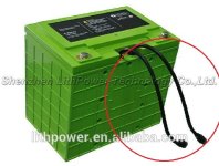
Can you tell me anything about this BMS?

mjp8081

100 W
Joined
May 12, 2009
Messages
164
Location
San Francisco Bay Area
Hello all,
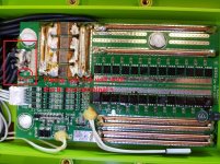
I have a couple bad BMS boards from a "drop-in replacement for lead acid deep cycle battery", 12v 4s ~100A Ch/Dch, 150Ah Charge/Discharge through same input/output, main terminal posts. It is probably a bad mosfet, possibly IC. From accidental short circuit.

The cells are fine, tested at good voltage.

Alternately, if someone knows where to buy a replacement with similar specs, that could be helpful.

I am having trouble getting replacements from the supplier in China.
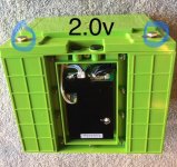
TEST VOLTS.jpg
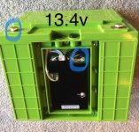
lith2v.jpg
lith13v.jpg
 
Are those LiFePO4?

If the FETs blew, either it would be always on or you would see some charcoal on one. More likely one of the voltage detectors blew and it thinks a cell is low all the time.

You can find similar units on eBay. Bestech Power is another possible source.
 
thanks for posting fechter
they are lifepo4

yeah there are no burnt ones

where is the voltage detector on the board and is it replaceable?

yes i was just perusing bestech

It is a bms/pcm that charges and discharges load through same 2 terminals, is that a specialized bms, or can any be wired to work that way?

thanks
 
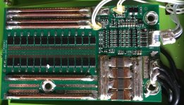
The tiny 3 legged or 5 legged parts around where the temp sensor wire goes in. If you had the right parts to replace bad ones, it might be possible to repair, but SMD rework is difficult.

That board style I call a one port, where you charge and discharge through the same terminals. There are also two port styles where the charge port is separate from the discharge port. They make both styles, so you have to pay attention to the layout.
 
thanks for that, one more question:

so this is a 4s configuration, but there are 5 fat black wires going in and out of the bms. What its the fifth wire?
 
mjp8081 said:
thanks for that, one more question:

so this is a 4s configuration, but there are 5 fat black wires going in and out of the bms. What its the fifth wire?

Each cell has two ends. For 4s cells, you need 5 wires. Another way to look at it is you have a battery negative, and each series cell has a positive.
 
I need to replace this, from a 4s60p "deep cycle lead acid auto/boat replacement"

150ah
Supposedly 100amp ch/dch
Single neg port/terminal, charge and discharge/load common input/output(no separate charging input) like lead acid.

One question is: why are there 5 wires going in and 5 out if this is a 4p? What is the 5th wire?

Anything else you can tell me about this BMS from the photo would be extremely helpful. I can get an exact replacement, but it would take many weeks and $130 each, and I'd like to get something that can handle more current with better fail safes. Originally, these batteries had some kind of separate input/output wires(SMBUS?)--see photo.

This one failed from a quick short circuit (neg wire touched pos terminal), but did protect the cells. Another BMS I have (I have 2 that need replacing) failed after I had 2 battery packs/BMSs in parallel, one at 13.2v the other at 12.6 when installed. The 12.6v pack's BMS read the 13.2v from the other battery. As the batteries depleted, the less charged batteries' cells went down below safe levels, it's BMS thinking their voltage was higher, at the higher voltage of the paralleled battery pack. I hope that makes sense. Now that pack wont charge above 10.8v or so. I'm just guessing that's what happened, and obviously I dont know much about BMSs. The BMS might have just been faulty, component wise. You can tell from the soldering these are not high quality BMSs.

Anyway, any input you have would be appreciated, thanks for reading.

IMG_0082es.JPG

lith2v.jpg

HTB1RFC.LpXXXXbh(08-25-09-34-54).jpg
 
Re: 5 wires = Battery negative, cell 1 positive, cell 2 positive, cell 3 positive, cell 4 positive = 5 wires needed.

Re: Batteries in parallel. What you described can't happen. Two batteries in parallel will create a current until they are equal. Unregulated, this can be very fast and can cause issues that way.

A 12v lead acid battery that won't go past 10.8v usually indicates a shorted cell.
 
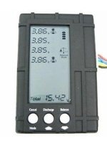
on the circuit board, where it says BO, thats always going to be the negative, then cell group 1,2,3,4. If you have a balance meter or similar that can read lipo batteries you can connect that 4s connector to it and it will give you a true reading of what each group of cells reads. If you have a balance charger that can charge lifepo4, you can charge it up that way before installing the new bms, that way your sure its properly balanced.
Like you mention maybe those bms might not be top of the line, like they use on the more expensive lifepo4 batteries. Some of the cheaper bms only balance at 50ma, if the battery isn't balance to begin with, it won't perform to its maximum.

lifepo4 12.8 volt 4s

Fully charge voltage is 14.6 volts and fully discharge voltage 11.2 volts
each group cell max 3.65 volt, min is 2.8 volt


3in1.jpg
 
Thanks guys

Sunder said:
Re: 5 wires = Battery negative, cell 1 positive, cell 2 positive, cell 3 positive, cell 4 positive = 5 wires needed.

I should have been more specific...there are fat 5 Fat (~12g) black wires soldered together touching, to the board going in and then out. Which I'm pretty sure one cant be positive.

Sunder said:
Re: Batteries in parallel. What you described can't happen.

So it was a bad BMS...man these things are crap. I'd really need a good replacement.

Are there BMSs that would have protected against a short circuit and not died?
 
Oh right. The 4 could be going to the 4P of cells, and the 5th going to the outer terminals of the whole battery. Hard to tell from the photo, but it looks like you have 4 going to the bottom right terminal, and the 5th goes further under the circuit board. I am taking guesses based on your photos though.

It gets confusing - Not all BMSes have short circuit protection, even though you'd think it's a basic function. However, all BMSes should have current limiting functions, on the discharge side though. If the resistance is zero, and the resistance of the batteries are very low, current limiting might not be enough. The BMS may die rather than shut down correctly.

Some BMSes also have short circuit protection on the discharge side, but not the charge side.

I'm not great at reading circuits, so I won't provide any advice on how you can tell, but apparently, there should be both input and output mosfets if there is short circuit protection on both sides.
 
Thanks sunder
yeah its 5 black wires all connected/soldered to the board "in", and 5 soldered together coming from the out point of the board (then going underneath back to the cell pack) 10 total 12g neg wires.
 
Back
Top