When experimenting or using parts from different sources, we frequently find the color codes on brushless motors and controllers do not correspond correctly. Just because the right colors are present does not mean they will match correctly, though that would be a good first guess.
Most brushless motors used on bikes, scooter, and motorcycles have 3 phase wires (the fat ones that take the power) and 5 hall sensor wires (the skinny ones). Some motors may also have a temperature sensor or shaft speed encoder (more wires).
The problem is how to determine which wire goes where without blowing anything up...
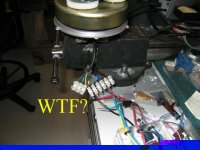
If full power is applied to the controller and the wires are not properly connected, there is a very good chance of destroying the motor, controller or both.
There are typically 3 hall sensors in the motor that tell the controller the position of the rotor.
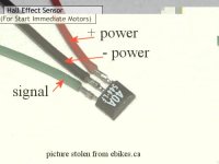
Each sensor has a + and - power lead and a signal output. The first thing to sort out is the hall sensor power. The controller will supply a votage to the sensors that is typically between 5v and 12v. The most common color coding for the hall power is red= positive, black= ground.
If there are no black and red wires, or it is not clear which are the power wires, it may be necessary to open the motor and trace the wires going to the hall sensors. The hall supply wires will branch off and go to all three sensors. If + and - are not black and red, then it may be necessary to look up the datasheet for the hall sensor to determine the power connections.
Here is the most common style of hall sensor used in motors. This one is a Crystalyte:
Here's what the hall sensors look like in a Kollmorgen motor:
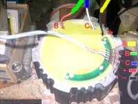
Now, once the hall supply wires are sorted out, it's a matter of matching the phase and signal wires. If the colors of the remaining wires seem to match, that would be the obvious first try.
When testing unknown wiring combinations, it is important to somehow limit the current that the controller can get during testing. If one wire is out of place, the current in the controller could be very high and cause the controller to blow. Testing with the batteries connected to directly to the controller is very risky.
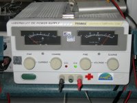
The best approach is to use a bench power supply capable of enough current to run the motor at no load. This is the one I like to use:
If you do not have access to fancy, expensive test equipment, then you should put something in series with the batteries to limit the current, but still allow enough to run the motor at no load without tripping the low voltage cutout on the controller. At no load (wheel off the ground), most bike motors will draw around 2 amps or less. Larger motors may be up to 5 amps or more.
You could use a 5 amp fuse or circuit breaker if you have nothing else. A large resistor, like a car headlamp may suffice in a pinch.
You also need to measure the battery current while testing. This is very important, since you want to back off the throttle immediately if the current starts going too high, and it's about the only way to tell when you have the right wiring combination.
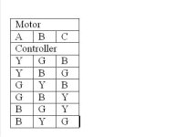
For the 3 phase wires, there are 6 possible combinations of wiring to the controller. It is good to use a piece of paper to write down the combinations so you can keep track of which ones have been tried. For each phase combination, there are 6 possible hall signal combinations. This gives a total of 36 possible configurations that may need to be tested.
If we label the motor wires A, B, and C and the controller wires Y (yellow), G (green) and B (blue), the combination table looks like this:
For each attempted combination, apply power and slowly advance the throttle while watching the current.
Incorrect combinations will have different effects depending on the combination.
Some combinations will result in the motor vibrating or not moving, but the current rises rapidly with throttle... bad.
Some combinations will result in the motor running, but the current will become excessive at higher speeds... bad.
Some combinations will result in the motor running backward... bad.
When you get the right combination, the motor will start from any position, run forward and the no-load current will be in the 'expected' range.
Be very careful when swapping the hall signal wires around. If a hall signal wire makes contact with the hall supply, there is a good chance of blowing the hall sensor. Best disconnect all power before swapping wires.
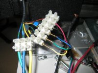
When swapping wires around, I found it very handy to use a barrier strip terminal block to hold the wires. In this setup, I used some connector pins from a serial connector to make swapping even quicker.
Hope this helps, and happy motor testing!
Most brushless motors used on bikes, scooter, and motorcycles have 3 phase wires (the fat ones that take the power) and 5 hall sensor wires (the skinny ones). Some motors may also have a temperature sensor or shaft speed encoder (more wires).
The problem is how to determine which wire goes where without blowing anything up...

If full power is applied to the controller and the wires are not properly connected, there is a very good chance of destroying the motor, controller or both.
There are typically 3 hall sensors in the motor that tell the controller the position of the rotor.
Each sensor has a + and - power lead and a signal output. The first thing to sort out is the hall sensor power. The controller will supply a votage to the sensors that is typically between 5v and 12v. The most common color coding for the hall power is red= positive, black= ground.
If there are no black and red wires, or it is not clear which are the power wires, it may be necessary to open the motor and trace the wires going to the hall sensors. The hall supply wires will branch off and go to all three sensors. If + and - are not black and red, then it may be necessary to look up the datasheet for the hall sensor to determine the power connections.
Here is the most common style of hall sensor used in motors. This one is a Crystalyte:

Here's what the hall sensors look like in a Kollmorgen motor:

Now, once the hall supply wires are sorted out, it's a matter of matching the phase and signal wires. If the colors of the remaining wires seem to match, that would be the obvious first try.
When testing unknown wiring combinations, it is important to somehow limit the current that the controller can get during testing. If one wire is out of place, the current in the controller could be very high and cause the controller to blow. Testing with the batteries connected to directly to the controller is very risky.
The best approach is to use a bench power supply capable of enough current to run the motor at no load. This is the one I like to use:

If you do not have access to fancy, expensive test equipment, then you should put something in series with the batteries to limit the current, but still allow enough to run the motor at no load without tripping the low voltage cutout on the controller. At no load (wheel off the ground), most bike motors will draw around 2 amps or less. Larger motors may be up to 5 amps or more.
You could use a 5 amp fuse or circuit breaker if you have nothing else. A large resistor, like a car headlamp may suffice in a pinch.
You also need to measure the battery current while testing. This is very important, since you want to back off the throttle immediately if the current starts going too high, and it's about the only way to tell when you have the right wiring combination.
For the 3 phase wires, there are 6 possible combinations of wiring to the controller. It is good to use a piece of paper to write down the combinations so you can keep track of which ones have been tried. For each phase combination, there are 6 possible hall signal combinations. This gives a total of 36 possible configurations that may need to be tested.
If we label the motor wires A, B, and C and the controller wires Y (yellow), G (green) and B (blue), the combination table looks like this:

For each attempted combination, apply power and slowly advance the throttle while watching the current.
Incorrect combinations will have different effects depending on the combination.
Some combinations will result in the motor vibrating or not moving, but the current rises rapidly with throttle... bad.
Some combinations will result in the motor running, but the current will become excessive at higher speeds... bad.
Some combinations will result in the motor running backward... bad.
When you get the right combination, the motor will start from any position, run forward and the no-load current will be in the 'expected' range.
Be very careful when swapping the hall signal wires around. If a hall signal wire makes contact with the hall supply, there is a good chance of blowing the hall sensor. Best disconnect all power before swapping wires.
When swapping wires around, I found it very handy to use a barrier strip terminal block to hold the wires. In this setup, I used some connector pins from a serial connector to make swapping even quicker.

Hope this helps, and happy motor testing!


