X5 motor repair: When good dropouts go bad!

lazarus2405

10 kW
Joined
Sep 5, 2007
Messages
782
Location
Rochester, NY
This topic was copied from here:http://endless-sphere.com/forums/viewtopic.php?f=2&t=3711 See this thread for further comments.


Title says it all. Sure I thought they were great. They were 8mm wide! But, aluminum. My axle slowly ate away until it came loose in the wee hours of the morning, on a pothole, on a sidewalk, at 10mph, 15 feet from the bike's home.

So, I've proceeded to begin troubleshooting. At least one phase wire is severed at the axle (hanging by insulation). Another is at least 1/4th severed. The remaining phase and Hall wires are all intact. When I repair this, what should I know? Will there be an obvious place to attach new wires? What method should I use to attach the new wires? What gauge can I fit out the axle? Ad, most importantly, how do I remove the damn side covers?! I have all the screws on both covers removed, and nothing moves one bit.

As far as I know, that is the only thing damaged. The motor cut out very quickly because the tension created on the phase wires disconnected the Andersons. I can perform any tests that would be helpful. I can say now though that the motor has very high rolling resistance in both directions. When everything is connected, with the damaged phase wires, the bike does not respond to throttle. Not a twitch or jerk or turn. Everything else appears normal. I suspect the simplest explanation of this is that that second phase is a lot more than "1/4th severed".

What do I need to look for outside of the motor? Could the controller have been damaged?

And yes, this means that I am getting torque arms now.... :roll:

Edit: I can take pictures with my webcam, since the darn thing (motor, that is)is in my dorm room now. Damaged wires first, then any requests the hive mind might have.
 
Ouch... thank god that did not happen at 30 mph ( Or on a FRONT fork !! !!!! :shock:

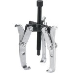
Do you have a 3 jaw gear puller ?

edit to add : once the screws are removed, you need to break the paint layer that holds it all together.. take a blade knife and cut the paint along the hub cover..

then use the puller to push the axle thru the magnet ring/spoke flange.

If you don't have a puller.. you can try placing the motor on it's side on the floor, axle on the floor, motor horizontal ( not your nice hardwood floor if you value your life and married ) and push the manget ring down..

WATCH YOUR FINGERS.........the magnets are strong !
 

Attachments

  • 3jawpuller.jpg
    3jawpuller.jpg
    12.3 KB · Views: 8,235
The wheel didn't actually leave the frame. Just the axle was no longer stationary. Eek. Anyway...

I see that it's possible that the two damaged phase wires might have shorted together against the axle. What would have been the result of this? Do I need to be afraid?

Edit: What size puller will I need? 4"? 6"? And... um... on the motor, which bits go where? The rotor flange need to be pushed out off the stator one way or another... Having never opened a hub, I can't see where the jaws and bolt hook, nor can I see where the force is applied to the puller.
 
The threaded black centre rod will push on the axle.

the 3 jaws hold the spoke flange on the magnet ring.

When you twist the centre rod, the stator with copper windings, axle and all will push the oposite cover off the magnet ring.

Again : Please be careful, and watch your fingertips ! :wink:
 
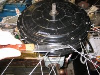
The side covers are usually stuck on with the paint. Once you remove all the screws, I used a pocket knife and a hammer to break the paint seal. Once you tap the blade into the crack far enough for the paint to let go, you can use a screwdriver to finish prying the side cover off.

You need the gear puller if you want to remove the stator from the rotor. You may be able to repair everything without doing this.

When the wires twist and short out, several bad things can happen. You could possibly blow the controller, and you could possibly blow the hall sensors inside the motor.
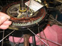
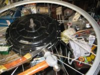
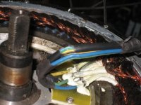
That's what happened to the one in these pictures:

Cracking the motor cover open1.jpg

Cracking the motor cover open2.jpg

Motor wires inside.jpg
 
When the wires twist and short out, several bad things can happen. You could possibly blow the controller, and you could possibly blow the hall sensors inside the motor.

I was afraid of that. I think the controller is fine but the hall sensors might be damaged. When I had everything connected and powered on and pushed the bike, CA gave erratic speed reading. It would jump from 20 to 45 to 30 to 15 and after about 15 seconds it would settle back to a semi-accurate 5mph.

If the Hall sensors are blown, where do I locate them? How many are there, and what should I expect to find if one or more is blown? As far as I know, they would look something like a blown FET, somewhere on the outside of the stator.
 
Hey fechter, was that motor mine? I thought the hall sensor just got pulled off instead of actually shorting.

In any case, with my motor the wires had all seemed physically fine without opening the motor, so if you can actually see that even the thick phase wires got torn apart, lazarus, then things look grim.
 
CGameProgrammer said:
Hey fechter, was that motor mine? I thought the hall sensor just got pulled off instead of actually shorting.

Yes, that was your motor. The hall wires shorted out and blew the green hall sensor. At least it was only one.

When they blow, there is no visible sign, the output just stays low.

Testing them is sort of a pain because the connector pins are hard to probe with a meter. I'll post more later...
 
So I have the stator removed and in my lap now (Hey, it impressed one roommate...). I tested continuity between the solder points on the phase wires and each corresponding Anderson. Look like none of the wires are actually severed, but they are ~1/3 of the way cut into. Might as well replace them with 10awg while I have it open. Though, now I know that my problem isn't so simple.

I can see now that the stator is out that there is a defect in the axle at exactly the place where the two phase wires were damaged. Looks like there was a decent spark. Rut roh.

So either it's the hall sensors, or the controller, or both. How can I eliminate one or the other possibility?

If it's the hall sensors, can they be easily replaced? I found them on the stator, and they're pretty small, but the wiring is self-explanatory +v/gnd/sig. l'd rather not mail the whole stator just for those little buggers.

If it's the controller, would it just be blown FETs? On the low side? Or where? If it's a FET problem, would it be blown or just stuck?

Thanks again folks...
 
I havent posted in a while, but being retired leaves me practically no free time! I also recently spun a motor, P2A in rear steel suspension trike. I had to go to Walmart and buy a cheep suspension bike to get a new rear triangle. The factory was twice as expensive as the whole bike for just that part. My wires were very twisted, but not severed. Of course, this is one of the joys of brushed motors! I did take the motor apart, but decided to re-insulate just the parts of wire coming out of the shaft. I also had my local machine shop rethread the worn axle side, which was the cause in the first place. When I rebuilt, I finally installed that old torque arm I bought a year ago. Shoulda done it a year ago. Works as good as new, now. I also got some slightly higher range gears and a spring that gives more suspension travel. The remainder of the Walmart bike was put out as trash, but was picked up by locals in about 10 minutes. Dont know where they will get the parts I removed!
David
 
I'm going to turn this into a tutorial thread...
Anytime you spin the axle in the dropouts, the wires can get cut through, or stretched apart. Sometimes a stretched wire will make an intermittant contact, which can blow your controller.
A short in a hall wire can blow the hall sensor inside the motor. Do not try to run a motor that has been spun out before checking all the wires first.

Damaged wires can easily blow you controller!

Backing up a step, After you pry the covers off, try to slide the bearing off the axle. Ususally they'll slide right off, but sometimes they're stuck on pretty good. Do not use a hammer or pry against the side of the bearing to avoid denting the dust seal. A gear puller is the best way to get stubborn bearings off.
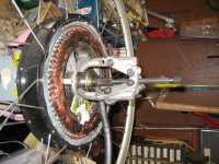
Pulling the bearing.jpg

You can visually inspect the phase wires for damage. If damaged, they can be replaced. If just the insulation is cut, you may be able to slide some heat shrink tubing over the area to protect it.

On the other side, you can access the splices for the hall sensor wires.
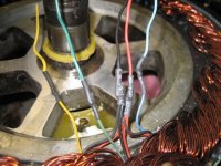
Hall wire splices.jpg

Using a sharp blade, you can carefully slit the heat shrink tubing and remove it. From here, you can measure continuity to the connector. With the mini XLR style connector, it is difficult to get a meter probe on the pins, so I used a short piece of solid strand copper wire to back probe the pins on the connector. If you take apart the connector body, you can get to the backside of the pins. You can jam the end of the solid wire into the heatshrink and push it in far enough to make a connection to the pin. From there, the other end of the wire can go to your meter. You need to check for shorts between wires too. This is worse than a broken wire.
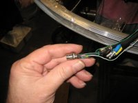
Back Probing the connector.jpg

To test the individual hall sensors, you need to apply power to the black and red wires.
Something between 5v to 9v will work. You could use a 9v battery if you don't have a power supply. An accidental connection between the +power and the hall signal wire when the output is supposed to be low will destroy the hall sensor, so be careful to insulate the wires from each other.

With +5 going to the hall power wires, you can measure the voltage from each sensor signal wire (the yellow, blue, green wires) to the black wire. With power applied, the output will toggle between high and low when opposite ends of a magnet are put against the sensor. You can use about any small magnet to test with. Strong ones are better.
I measured .02v for a low, and around 3.5v for a high with 5v power.
A dead sensor will be stuck low usually. If the sensor does not toggle when you reverse the magnet, it is bad.

If you locate a bad sensor, you will need to replace it. They are glued in with epoxy. To remove the epoxy, it is very helpful to heat it first. You want to be careful not to overheat and melt anything, but if you get the epoxy up to around 100C, it gets sort of soft and rubbery. Using a very small bladed screwdriver, I dug the epoxy out. Since the old sensor is trashed anyway, it's OK if it gets destroyed in the process. Completely clean out the slot where the sensor sits so the new one will fit.
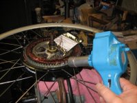
Heating the epoxy.jpg

Digging out the epoxy.jpg

You can buy new hall sensors from ebikes.ca, Digikey, or a number of other places.
The sensor is a Honeywell SS40A. Digi-Key Part Number 480-1998-ND
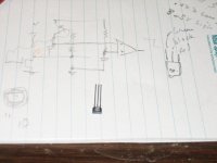
New Hall Sensor 1.jpg

Next, I attached the wires from the old sensor onto the new sensor. This is a bit tricky, since you need to keep the solder connection narrow enough so the wires won't touch each other when you place it.
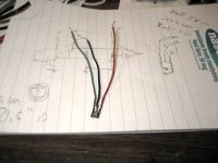
New Hall Sensor with wires.jpg

Feed the ends of the wire back through the same slot they came out of and carefully bend the wires so the sensor fits into it's slot. I used a dab of super glue to hold the sensor in place before epoxying it.
View attachment 3

Once the sensor is tacked in, I used a piece of scotch tape over the slot to make sort of a 'dam' to keep the epoxy from running down the face of the stator. With the tape in place, I burried the sensor in epoxy. I used regular 5 min. stuff. The epoxy runs down the sides of the sensor and fills in the dam, then hardens. After the epoxy hardened, I removed the tape.

You could also just let it run down and file off the excess after it gets hard. You want to make sure none of the wires or the sensor will rub against the rotor when you put it back together.
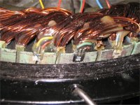
New Hall Sensor epoxied in.jpg

Now about all that's left is to reconnect all the wires. I used a completely new cable for the hall sensors. If the old one is long enough and you cut off the bad part, that would be easier.
I used heat shrink tubing over all the connections. All the black wires go together, and all the red wires go together.
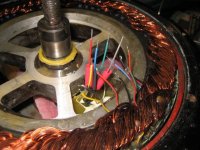
New Wires ready for connection.jpg

It would be a good idea to re-test the hall sensors before shrinking the heat shrink
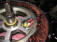
New wires finished.jpg
 
Back
Top