Adaptto Mini-E/Max-E Owner's Thread

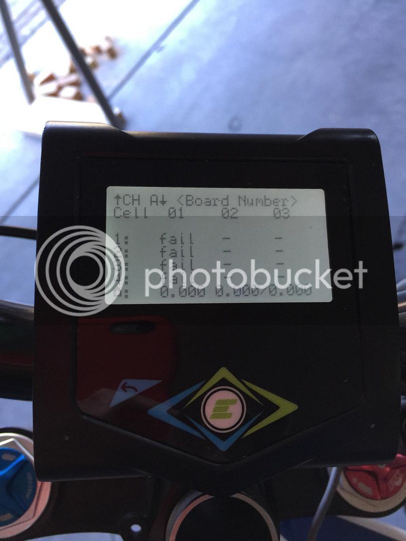
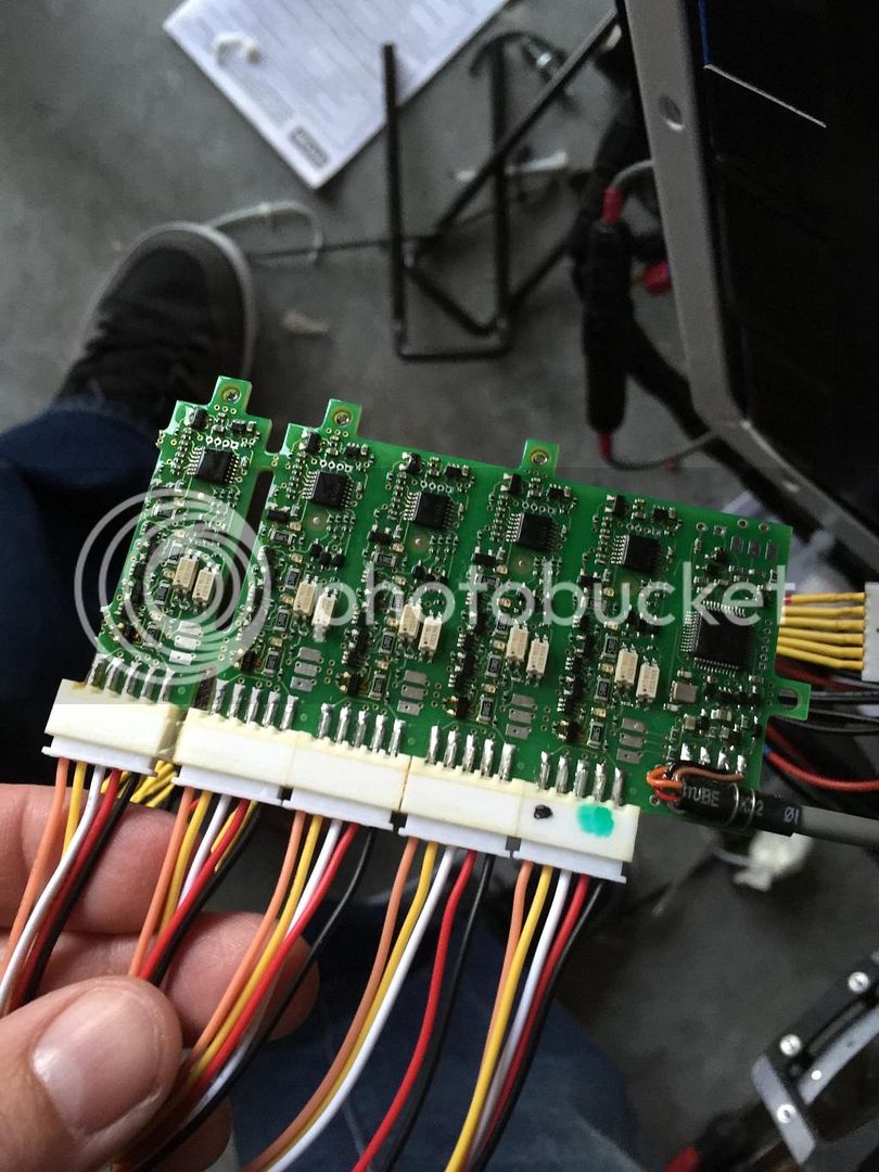
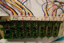
As we all suspected, it was the connector.

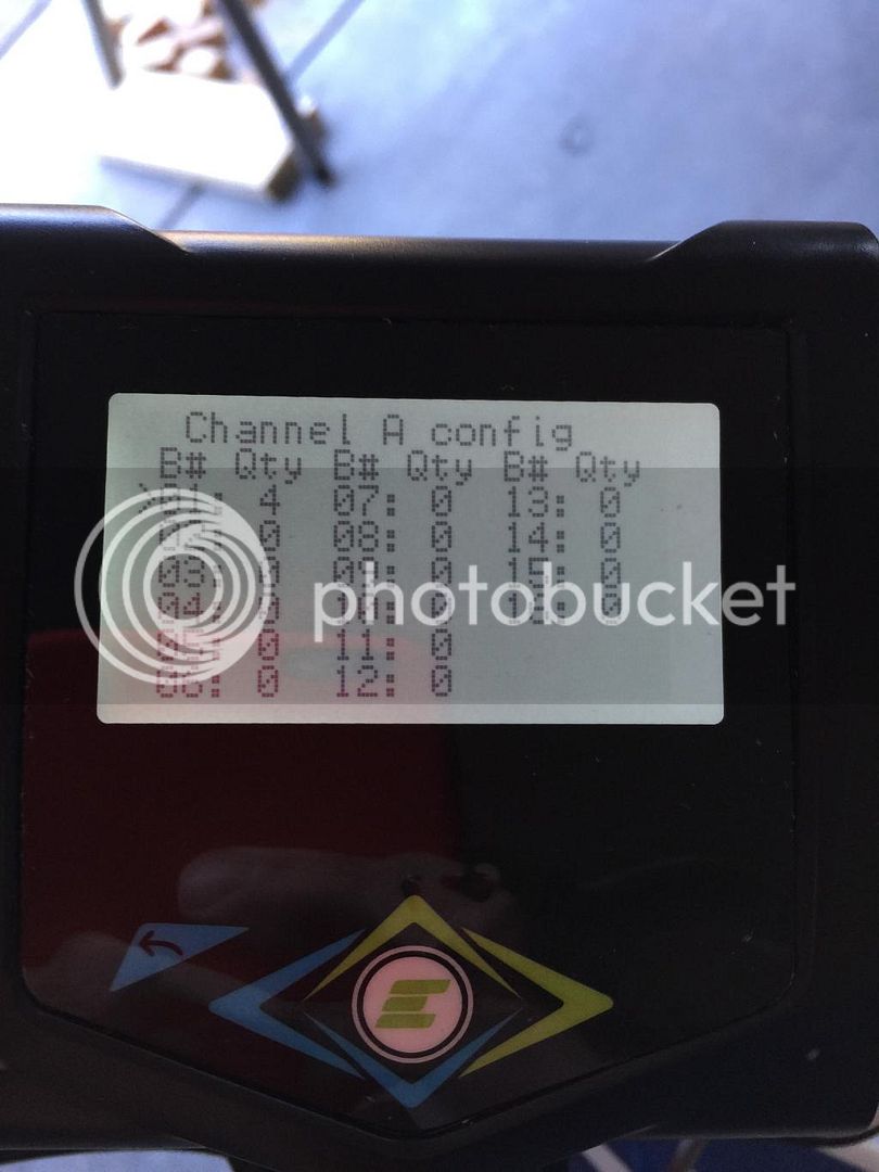
Oleg from Adaptto suggested that I apply a very small bend to the pins on the male side of plug. So I took a small flat blade screw driver and just gave them all a 1mm push to the center. After that I had a good connection and was able to get the auto calibration done.

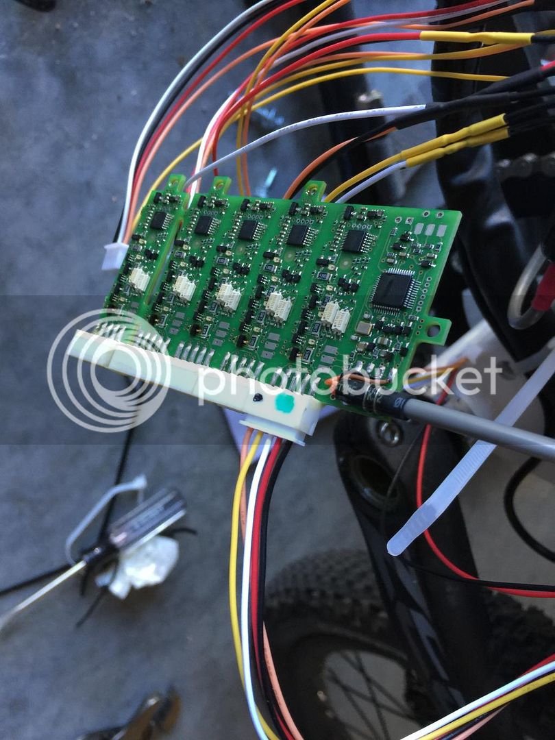
Today I hope to get the BMS wired... Going from 5s packs to 4s plugs looks fun :?

Thanks for the help and suggestions guys.
 
good to see you got it working. however, on mine it was no bad connection but a bad solder joint. I already have alert Adaptto about this problem more than one year ago..
 
Yesterday I have installed my BMS and the balance connections are perfect for the first time :D .. no short or reversed connections.. on these "easy" pcb connections.

It work perfect and I have configured everything... BUT! now I'm getting s strange problem:

BMS is connected and work fine but when I push the throttle, in ECO mode the motor barely rotate and have no power... the NORMAL mode does nothing.. and only the BOOST mode is working ! ??

Look like a firmware error? I have the lastest version RC9e.

also every time I power ON the adaptto from the normal sleep mode it display !BMS! for few second and then disappear...

In the BMS log I have no error detected and all the cells voltage are OK ( about 4.040V +/- 3mV) and the LVC is set to 3.0V and critical LVC is set to 2.8V. Balance is set to 4.140V and full charge is set 4.150V)

Any idea about that problem with ECO and NORMAL mode with reduced or inexistent power problem??

Doc
 
Doctorbass said:
also every time I power ON the adaptto from the normal sleep mode it display !BMS! for few second and then disappear...

This is normal, or at least how mine behaves. I think the display isn't showing that connection to the BMS for a couple of seconds while the controller is waking up.

Doctorbass said:
Any idea about that problem with ECO and NORMAL mode with reduced or inexistent power problem??
Doc

What settings do you have for ECO and NORMAL on the "Profiles" screen? My settings were very low by default and I had to raise them quite a bit in the Profile menu to make the bike more usable.
 
Hey guys, I'm hoping someone knows a bit more than me about this BMS setup, because I seem to be struggling to get this worked out.

I am running 20s Lipo in 5s packs. I have reduced this down to 5 connectors of 4s for the BMS.

I plugged this all in to the board. (Board is unplugged)

And I notice the board is getting warm. It's not smoking or sparking, just getting warm / hot like it would if balancing.

I figured it needed to be connected / configured, so I plugged in the board and enabled it under the BMS screen.

Then I set the Board 'A' to have 4 cells on blocks 1-5.

When I checked the status, I see 'fail' on all cells.
 
After that, I think crap something's wrong and pull all 5 balance plugs out...

After resetting the BMS to enable only board-A, block-1, with 4 cells... I plugged in a single balance plug and checked again.

D8581F61-589C-4B9B-A128-0EB24B31C66D.jpg


E3F24BC1-DAFB-48CE-BC83-626A5D77A747.jpg


E6037140-BB4D-49F9-98CF-0B6BBD9E0F89.jpg


AEB8C9BC-8596-4056-887D-243039B26F35.jpg
 
Since then I have checked every balance connector and voltage reads correctly each cell being 4.15V higher then the next, till I reach the next plug.

Then the first pin / ground reads equal voltage to the previous plugs highest pin.

This repeats till the final pin is roughly 83V

So in this pic, the ground pin is the rightmost pin. Voltage increases as the pins move to the left, correct
D8581F61-589C-4B9B-A128-0EB24B31C66D.jpg
 
Doc, could it be the SPD smooth in the traction settings that makes it not spinning in eco mode? Try with different values. The highest did the trick for me.
 
yep thats correct, higher volts to the left.

the top cell voltage on each ballence plug is the gnd on the next board along, so make sure they are the same voltage.

go along each plug with the metre to check the voltages are all in correct order.

number the plugs on BOTH sides with a pen to make it easyer.

plug the bms in FIRST as in the instructions before plugging the ballence plugs in.

then plug them in 1 by 1 and the screen should show them coming on.

i found sometimes if there is an error BMS! because the voltage calibration is set wrong or such, power needs to be reset to reset the bms.
 
I did check all the voltages, and they are correct. It must have been that I plugged the ballance plugs in before connecting / enabling the BMS. When I get back home, I will make another attempt.

Thanks for your help.

ridethelightning said:
yep thats correct, higher volts to the left.

the top cell voltage on each ballence plug is the gnd on the next board along, so make sure they are the same voltage.

go along each plug with the metre to check the voltages are all in correct order.

number the plugs on BOTH sides with a pen to make it easyer.

plug the bms in FIRST as in the instructions before plugging the ballence plugs in.

then plug them in 1 by 1 and the screen should show them coming on.

i found sometimes if there is an error BMS! because the voltage calibration is set wrong or such, power needs to be reset to reset the bms.
 
Unfortunately, I was unable to get the BMS to work. I tried another BMS board from my MiniE kit and it was the same.

I'm out of ideas on this one.
BDEA74F9-DF1F-4314-A02E-9FC6E32693F0.jpg


7CFCD9C4-9230-46D1-986F-F99A602E7DF8.jpg


242F6F8E-CC7C-4BCA-B074-0EE47E9FFFEA.jpg


BD556A82-6DFC-4CAF-B9EA-CD9D7981523D.jpg
 
If you've tried another BMS with the same result and it looks like communication issue rather than a cell configuration problem, I would be looking very closely at the BMS connector on the controller side. Based on others experiences with intermittent connections on some of the plugs it would seem likely your issue is similar.
 
zlagger, is your black cable on the left Negative(on the right side of the connector in your picture)? In this case you have it wrong. You are holding the board wrong, turn it 180degrees and compare yours with the BMS picture from Adaptto again.
 

Attachments

  • DSC04547.JPG
    DSC04547.JPG
    82.5 KB · Views: 3,304
The !BMS! is to do with Adptto not using shielded cable on the BMS, when you turn on the system, and in my case on heavy regen it would flash up the !BMS! message, if you change the cable out with shielded cable, and ground the gauze wrap at one end on the bike chassis, it stops it, either that or you can get anti emf tape to wrap round the cable that has copper embedded in it, this is the same for the !HALLS! message that can appear under heavy regen, if you swap out the motor wiring for shielded cable, and ground one end of it it stops that message too.
 
This is my battery wiring thread for the BMS if you want to take a look >>> http://endless-sphere.com/forums/viewtopic.php?f=2&t=61059
 
zlagger said:
Unfortunately, I was unable to get the BMS to work. I tried another BMS board from my MiniE kit and it was the same.

I'm out of ideas on this one.

Ill find my thread again on this, I too shared the same dramas. I've got a few pictures though that show it step by step.

I eventually got the correct wiring but thought it i was wrong, so reversed it all!

Ended up buying 4s packs.
 
Thanks Allex. That was the problem. Not sure why it was flipped / not factory. BMS is working.

Allex said:
zlagger, is your black cable on the left Negative(on the right side of the connector in your picture)? In this case you have it wrong. You are holding the board wrong, turn it 180degrees and compare yours with the BMS picture from Adaptto again.
 
NYX bike & Adaptto BMS progress

I am finalizing the Adaptto BMS customization and installation on the NYX bike. The Goal are to get it very compact, have safe protected and idiotproof connections and locate it nicely on the NYX carbon frame.

Actually i have nearly finished for the BMS install, I have drilled the 22 holes thru the battery cover on the top of the frame, and have inserted some transparent hot glue into them to make a kind of Light pipe or "light guide" to take the LED light from the pcb and guide it to the top of the cover and it work very nicely!

More video to come!

[youtube]w7CWPgwaXzA[/youtube]


When all BMS bleeding resistors are working, the BMS dissipar a great amount of heat!.. On the back of the pcb am measuring about 65 degree C. I think i will install a heat guide with some flexible copper strip to sink the heat to teh aluminum cover with thermal paste to avoid it to overheat when confined inder the frame top cover and when there is the intense sun heat during summer. That willcertainly help. I will also add some 1/8" thermal pad in sandwich between the top of the PCB and the back of the aluminum cover.

Doc
 
Hello Doc
Good work.
Perhaps you use an normal "heat Silikon Pad" for getting the heat away from the bms.
But i think this is no problem, because normaly the bms does only work during charging, or parking the bike.
If you drive the bike - i think the bms does nothing.
There exists not many infos to the bms - but if it works - its okay.

If the bms have to work all the time, and produces to much heat - i think its better to replace the battery.
At my bike - the bms works only at the charging process - because i load up 14S to 58,6V - and the bms takes care that the cells have an max. V ov 4.18. But they have also a special sequenze that the resistor is not switched on all the time - but the resistors seems to be a little bit small
adaptto_bms_heat.jpg
I made a picture of the BMS during the balancing prozess - every cell 14 getting decharged down to 4.18.
As you could see the maximum temperatur is about 71°C
I could not measure the backside, because i also glue the bms to an fixture at my battery


Other question, does anybody uses also the adpatto with an Outrunner or an low resistance motor?
I have an new motor with about 19mOhm resistance - autoset works fine, the motor turns also fine on the bike, but if i go outside it takes about 2-4minutes until - i think the adaptto controller gets to warm , an reduce the power..
With the same motor system - but an other coil winding - it works - so i think the resitance of the coil is too less for the adaptto - has anybody info for me?
 
GreenRoad said:
Hello Doc
Good work.
Perhaps you use an normal "heat Silikon Pad" for getting the heat away from the bms.
But i think this is no problem, because normaly the bms does only work during charging, or parking the bike.
If you drive the bike - i think the bms does nothing.
There exists not many infos to the bms - but if it works - its okay.

If the bms have to work all the time, and produces to much heat - i think its better to replace the battery.
At my bike - the bms works only at the charging process - because i load up 14S to 58,6V - and the bms takes care that the cells have an max. V ov 4.18. But they have also a special sequenze that the resistor is not switched on all the time - but the resistors seems to be a little bit small

I made a picture of the BMS during the balancing prozess - every cell 14 getting decharged down to 4.18.
As you could see the maximum temperatur is about 71°C
I could not measure the backside, because i also glue the bms to an fixture at my battery


Other question, does anybody uses also the adpatto with an Outrunner or an low resistance motor?
I have an new motor with about 19mOhm resistance - autoset works fine, the motor turns also fine on the bike, but if i go outside it takes about 2-4minutes until - i think the adaptto controller gets to warm , an reduce the power..
With the same motor system - but an other coil winding - it works - so i think the resitance of the coil is too less for the adaptto - has anybody info for me?

Thanks for the pics! of the FLIR.

I wanted to maximize heat dissipation because i have squeezed my BMS board very tight and these are nerarlt all covered by aluminum box surrounding the pcb so the heat can not directly radiate to the air. With the thermal pad the BMS transfer the bleeding resistor pretty well to the cover.

About low resistance motor winding i can say that my actual 5302 is probably one of the hub motor with the lowest inductance and resistance. i did not drove it on yet appart on a DYNO so i can not comment on that. ( it's freeezing winter here -20 -25C). but the motor work well on a dyno.. lol...

My actual motor electrical parameters are:
--inductance bewteen two phases wires: 79uH with my meterman XR37 and 109uH(retested with calibrated Agilent LCR meter) 5 jan 2014
--DC resistance between two phase wire: 0.045ohm (direct to winding)

But the lowest the winding resistance is and the higher the inductanc eis the best efficient your motor is!

Doc
 
hello doc
the pics are no problem - i had the flir at the hand...
I think its interesting to know about the temperature of the bms.
i also have no good cooling situation - but i think its not realy important - i hope the adaptto guys know what they do.. :roll:
Buts its always good to stay cool....

To the motor settings... the adaptto settings of the autosetup are quit strange.
I get out differnt settings depending if the motor has an temperature of 20°c or 50°C - okay this could be normal and its physics.
But also interesting is, that i get out differnt settings of the fine Hall Offset, depending on the switched Phase wire.
Normaly i have 1 - 2° difference, but i also get out 13°if i use another Wire connection.... thats strange - because i do not know whats the right.

Tomorrow i should get an new Motor with another winding configuration - iam verry interested what settings i getting out.

The problem now is, that with the actual autosettings i only could drive about 1minute up to 50Amps, after that i also have a power of max 5A and i could stop the wheel with my hand - (Adaptto overheating protection?) - that means that something should be wrong with the settings but i do not know what that could be.
I used the same motor with more coil windings without any problem and now we reduce the winding - i get the problems.
 
Back
Top