The SB Cruiser : Amberwolf's 2WD Heavy Cargo Trike & Dog Carrier

HI AMBER,You have made a nice trike out of this and if you keep adding to it soon you will have the first motorhome trike that has ever been made. I really like your skills friend and I can see that if you had a fab shop with all the right equipment and new steel material there is no doubt that you could match any ones skills. keep it up. :lol: :D 8) :p :wink:
 
:lol: I actually know someone that's making a *real* motorhome trike, for him and his dogs, intended for cross-country exploration, minimalist-style, with a minimal electric assist. I keep hoping he'll post it up here but I haven't seen it yet.

I dont' do so well with minimal assist, so I am really gonna want to fix one of the 18FETs. The "12FET" I have on there now only does 25A peak, and probably 20A continuous...but that peak means it doesn't get moving very quickly. We'll see how things work once the controller from Dogman arrives; maybe it will do 40A and I'll get acceleration I can't outpace on my cane. :p


I didn't get very far in the lighting wiring last night, so more of that today when done wiht breakfast and waking up. Tiny actually let me sleep until about 40 minutes ago intstead of wakign me at dawn (or I slept thru it, which is unlikely :lol: usually the covers are all off the bed when she's done pawing them).

I did get a couple pics of the purple kennel interior lighting, which will look brighter when the inside of the kennel is painted white, which will happen someday.
View attachment 1

IMG_1462.jpg

I also had several "good" ideas aobut it as I was startng to doze, and I am beginnig to remember them but not qutie there yet.
 
I forgot to post the pic of the larger piece of debris that was in my eye (there were apparently two, as one is still there but it must be much smaller cuz it doesnt' irritate it nearly as badly). It is so small (less than 1/64") that I can't see clearly what it is even with magnification and sunlight, but it's color (though you can't see in the pic clearly) is that of the "dayglo yellow" frame paint of the toptube/headtube bit I used on the trike--I don't know for sure but it is likely when I was wire-brushing the dried-out Murray logo stickers off of the remaining bit of toptube that that is when it ended up under my eyelid. Explains why a magnet didnt' work to help move it.
IMG_1458.jpg

Ignore the doghair that snuck into the pic (I was afraid to try to remove it else I lose the debris piece before I got a pic, which took dozens of tries as ti was, using a magnifying glass between the camera and the debris to get it big enough to see even this clearly).
 
I figured it'd be almost as hot today as it was yesterday, and I have to do the wiring outside cuz I have to drill holes and weld brackets as I figure out where things go during the process, plus it's way easier to see small stuff to solder it if I am in sunlight...perks of gettin' almost to 47 (in a month). And indeed, it's been about 92 in the shade since 11am...but there's wispy clouds in the sun's part of the sky since then, so it hasn't gotten any hotter yet.
IMG_1484.jpg

So I built a little "awning" or whatever to shade the part of the porch area I will mostly be in (cuz that' teh only place the welder will reach with the cord out the back door from the distant dryer plug).
IMG_1474.jpg

It's just a quick and dirty job, but it still took me from about 930am? (whenever I last posted this morning) till abotu 11am to do it, thanks to my usual klutziness.
View attachment 5


These 1" square tubes (that i've been using to build various things from) that originally held signs are made to snap into each other to make a square, with "feet" taht then snap into brackets onto the shelving over the dog food aisles. A few years ago they took down the old red ones and tossed them (see the CB2 thread for where I hauled many of them home tied to it all over), to replace iwth larger tan ones. Some of the tan ones got tossed, too, cuz there were too many ordered or whatever. I saved one of them (wanted more but others got to them first).

The top of this is made from the larger tan one, built just like it would be for a sign, only it is horizontal, with the canopy tied to it. (canopy itself came to me via a storm wind several years ago, blown into the yard from who knows where). Has a silver side and a green side, I put the silver side up to reflect a little more sunlight than the dark green would.
IMG_1485.jpg

The uprights are made from four straight poles, that the end L poles insert into normally, plus half of one of the L poles welded right to the end of it.
IMG_1488.jpg


The L poles are 1" square tubing witha slightly smaller section welded perpendicular to it at the ends, so that smaller section fits inside the 1" straight poles. For some reason the tan 1" square tubing is thicker than the red stuff.

View attachment 2

Then I just tapped the L pole into the open ends of the corners of the tan frame, cuz it didn't just slide in due to the thicker tubing. I wrapped the corners in tape so it wont' tear the canopy; the edges are pretty sharp.
View attachment 1

Voila, "instant" canopy.


FWIW, I had a plan at one point to use several of the red frames, complete, to do essentially this, but held up without any poles on the yard side, just on the house side, with those welded to a frame that would be bolted to that nice heavy table there. But With some of the winds we get during storms, it'd probably tear itself apart. I'd need to bolt it to the house, and/or ahve the front legs going down into the ground some distance. I didnt' have enough tubing to do that and still use any of it to build other things from, so I never put the awning together.


As you can see I'm also braiding tree branches together so they will form a continous canopy overhead eventually, and I won't need an artificial one. But that isn't gonna be *this* year....
IMG_1473.jpg
 
Then, there is the little bit of work ont eh trike so far.

I got the rear ligthing installed, but not wired up yet.
IMG_1476.jpg


I took the towhitch light off CB2 (mangling part of the plastic bracket in the process, so I cut it off), and clamped it onto the top of the rear rack bar with a U-bolt that just BARELY fits over it (actually had to be forced onto it, squeezing the plastic, so ti can't come out). This will be the main tailight and brake light for the short run.
IMG_1478.jpg


I welded bracket tabs to the edges of the rear rack, drilled them for the turn signals, and mounted those on there. STicking out the sides like that they don't even come out farther than the edge of the kennel, so thre's no clearance issues--if the axle nuts fit, so does the whole trike.

Then I had a thought about those triangular harbor freight lights I'd gotten with teh plan to eventually use them on the trailer. I implemented the first part of the plan, which was to knock the magnet out (which has a handy 1/4" hole under it), and epoxy a bolt in there from inside, sticking out the back, long enough to go thru this 3/4" square tubing the rack is made from, and secure with a nut on the other side. The back cover is screwed to the front, so no worries about it falling apart from vibration.
IMG_1480.jpg

In fact you have to unscrew it to change the batteries...so this is the original batteries and the little magnet. Somehow I didn't get the pic of the internals and the bolt. :/
IMG_1482.jpg


The next stage would be to wire them up to a 4.5V DC supply from teh bike itself, but that has to wait till later; I don't have one handy that runs off DC correctly at my midlevel pack voltage.

Then bypass the driver chip and momentary button so the LEDs are directly powered from a switch setup on the "dashboard" so the white LEDs can be switched on for turn signals (using amber covers over them, or replacing them with amber LEDs if I had any), and the red LEDs are wired as tail and brake lights.

Ideally the red LEDs would also blink with the turn signals...I'd probably need to make a transistor setup to drive them all separately for thei different functions, with diodes to block the functions of brake or tail from the non-red LEDs, butnot block the turn signals from any of them.

Too complex for the moment.


This si the flasher unit,
IMG_1491.jpg
to be wired up to the Fusin kit's handle bar switch that includes something like a turn signal switch (though it didn't come with them). It also has a headlight switch and a horn button. I dunno if that switch will handle a car headlight, so I will use it to turn on the downlighting instead.
IMG_1483.jpg

The headlight will be switched just like CB2, with this, to switch ffrom center-off to brgiht or normal headlight. Presently I only have a single-filament headlight on there but I can add the other later--it's teh same housing, so just replace the bulb unit.
IMG_1481.jpg

This is what's left of the LED MC tailight I screwe dup by putting a too-long screw thru into the metal plates teh LED sare moutned to, whch shorted some of them to the grounded frame at one side and direct power to the other, so several are burned out. I have ot see what can be saved and maybe move some around to make the whole thing work but at a lower brightness perhaps.

IMG_1492.jpg
 
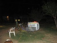
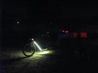
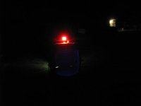
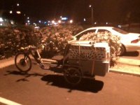
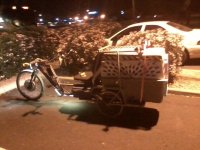
The trike is "finished" for stage 1, rideable on the street "safely", with motor, pedals that sort of work, and lighting with turn signals brake light, etc.

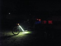
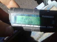
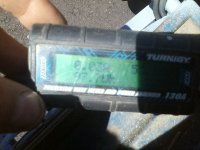
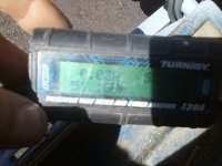
Wiring is all tied down (was too dark to get good pics, so all I got was pics of thelights. I took 2 versions of each pic I think, the darker ones were auto ISO, and the brighter ones were "high" ISO (I don't know what ISO on this camera though it might be 1000).


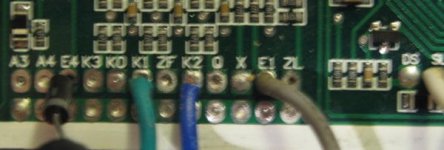
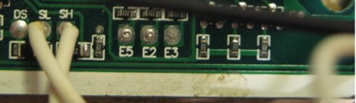
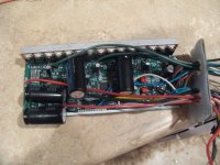
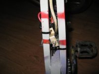
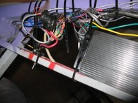
I spent way way too much time on the controller / motor wiring section, trying to make things neat, which is sort of pointless if I end up swapping over to the new controller...heck, evne ujust testing the new controller will require undoing my neat heatshrunk splices (I soldered all the wires, since nothing had compabible connectors anyway).

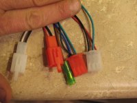
In the process, though, I found that the motor's andersons on phases were spliced on there off of some other motor (or controller), as the last few inches of wire were a different insulation type than the motor end of it. I only saw this cuz I unwrapped the tape and covering near the andersons as i intended to cut them off, and would need to splice in...then I saw the covering had been raggedly cut and that's why it was taped. I tried tot ake pics of the splices but everythign came out too blurry to see, and I cant' fgure out why.

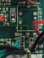
Anyway I cut the whole spliced sectin off, trimmed the LOOOONG controller phase wires down by a foot ro two, and spliced in there. Then I did the same for the halls.

Of course, I had to redo the phase wires TWICE, after I'd soldered them, becuase both times I put htem all color to color, isntead of B&G swapped. :roll: :oops: Only noticed as I was about to heat up the shrink.


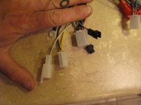
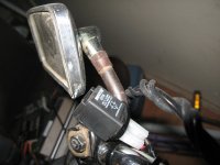
For the handlebar wires I used an old parallel printer cable, with the ends cut off, cux it has at least 25 wires in it, plus shield ground. I used pairs of wires for the turn signals, 12V and ground, and individual wires for throttle and ebrake. The flasher is on the bars for wiring practicaltiy, tied next to the mirror mount.

About halfway thru the wiring I just got too tired to be neat and careful anymore, and started just splicing and electrical taping.


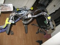
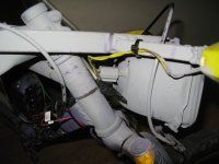
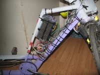
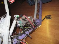
I did run the main power cable from the battery thru the frame, in the 'red toptube" just above the pedal chain. I used a 3-wire 12g (I think) power cord, so that 12V for lighting can go thru it as well as "48V" motor power, sharing the ground wire.

I was going to also run the rear lighting cables thru it, but I couldn't get my hands to work right (kept going numb at the wrong moments) while feeding it thru, and always jammed it somewhere down the line. Have to redo that later sometime. For now it's fed under the tube and tied to it to keep it out of the chain.

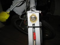
Headlight switch was gonna go on the bars, but there's no way those littel parallel cable wires (24g? less?) even doubled up are gonna take the current that thing draws without heating up, and I'm afraid of damaging other wires in the bundle. Turn signals are only momentary 50% duty cycle and much smaller so I'm not too worried abotu them, but th 50W headlight...is another story. So the switch went into the gap between "mixte" tubes, near the base above the cranks.

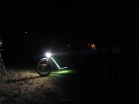
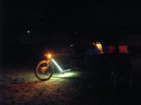
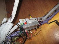
All the wires are fed into that area where I'd had the controller strappe dwon, and now that is ziptied in place (will make a mount bracket welded on the frame when I know what controller will go there). Wires are tied down to the downtube inside that area, and the bottom/front face of the downtube has the dowlighting flexiLED white strip.

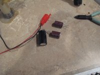
That strip is for 12VDC, and I don't wanna burn it out, so since I use 4s 16.4V for the main lighting, I put a 12V zener and some parallleed power resistors to allow enough current to it without heating up too much.

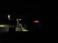
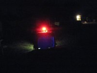
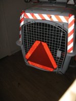
Turn signals and headlight get straight 16V out of the system, as does brake light. But tailigith has 4 diodes in series with it, and brake llight swithc (an old ebrake handle for now till I build a relay, if I do). basically just shorts across the diodes to brighten the LEDs some. I'm probably gonna add at least one more diode, cuz ther'es not that much difference in brightness maybe 1/3? Where it ougth to be 2/3 (I mean it ought to be more than twice as bright as brake than tail).

It's plenty bright with the triangle lights plus that, so no worries about dimming it a little.


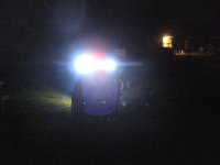
I also tried out the white LEDs in teh trinagle, and they are bright bright. Too bad I can't use them all teh time in teh rear.


I rode around the block a few times with teh lights on to find any vibration/loose wire problems, and found none so far. Ddid find I'd made the headlight wires like an inche too short, cuz an extreme right turn pulled the healdlith connetocr off the blubl. fixec by splicing in another few inches of wire.


Still need to add the toolbox to it, but have to work tomorow before midday and am too tired to do anythign with it now, so probaly not gonna ride it to work. Realy wanted to, so am sad. :(
 

Attachments

  • IMG_1493.jpg
    IMG_1493.jpg
    34.7 KB · Views: 6,462
  • IMG_1494.jpg
    IMG_1494.jpg
    11 KB · Views: 6,462
  • IMG_1495.jpg
    IMG_1495.jpg
    14.9 KB · Views: 6,462
  • IMG_1497.jpg
    IMG_1497.jpg
    21.1 KB · Views: 6,462
  • IMG_1498.jpg
    IMG_1498.jpg
    21.6 KB · Views: 6,462
  • IMG_1499.jpg
    IMG_1499.jpg
    28 KB · Views: 6,462
  • IMG_1504.jpg
    IMG_1504.jpg
    28.1 KB · Views: 6,462
  • IMG_1505.jpg
    IMG_1505.jpg
    24.3 KB · Views: 6,462
  • IMG_1506.jpg
    IMG_1506.jpg
    7.3 KB · Views: 6,462
Getting nicer and nicer! Freaky hot weekend it was.

Re the shit in your eye. At one point I was ready to dope slap you, and say. "where's your eye protection when you use the grinder?" But I thought to my self, "he's not a noob, like wearing a helmet it's his choice."

But really man, get some cheapo safety/lab glasses for the grinding, brushing, etc.
 
I've taken cheap safety protective eyewear (I like the ones with soft nose trips), drilled out a few 1mm holes as inflow & outflow and eliminated the annoying fogging that happens during rides. Shatter resistant, anti fog, UV protected eyewear for some chump change :wink: . My Rx sunglasses got the treatment as well, shortly thereafter. 8)
 
Keep rinsing your eye with salt water till you know that paint chip is out. Then get some cheap safety glasses to grind with. Harborfreight sells them for a buck apiece.
otherDoc
 
Lebowski said:
with all them lights: disco inferno on the WolfMan trike :shock:
:lol: There will be more later as I find them cheap or make them. ;)


dogman dan said:
Getting nicer and nicer! Freaky hot weekend it was.
Still hot...but of course nothing on summer. :(


Re the shit in your eye. At one point I was ready to dope slap you, and say. "where's your eye protection when you use the grinder?" But I thought to my self, "he's not a noob, like wearing a helmet it's his choice."
Usually I do wear it, I just got into doing stuff with you here and forgot to get them out. Stuff that breaks my routine means I screw stuff up and forget things...until I build a new routine around it. My whole vacation was like that, cuz I didn't have to get up and go to work and come home and all that, and so it broke both my routine and the dogs, and took a week or more to get a new one...by that time you'd already left.

Sometimes, it's better to say something anyway...but this didnt' happen while you were here, so it doesn't matter anyway. ;)

Helmets, though...I don't know exactly when, but somewhere along the line after work really changed, is when I stopped wearing mine. I'm not exactly sure why, either...I am not really wanting to dig into my possible subconcious reasons...they look pretty ugly when I peek in there. I tell myself it's cuz it's hot, and restricts visibility and hearing, etc., but I don't think that's it, cuz Iv'e always worn helmets and theyv'e saved my life at least once for sure, probably several times.


But really man, get some cheapo safety/lab glasses for the grinding, brushing, etc.
I've got some, but these bits bounced around them and got in anyway. :/

Now I am using some underwater-type glasses I had around that seal against my face. They suck for visibility on anything that's not right in front cuz thats the only clear part (and they are also tinted) and they are hot, but nothing can get in, even dust.


melodious said:
I've taken cheap safety protective eyewear (I like the ones with soft nose trips), drilled out a few 1mm holes as inflow & outflow and eliminated the annoying fogging that happens during rides. Shatter resistant, anti fog, UV protected eyewear for some chump change :wink: . My Rx sunglasses got the treatment as well, shortly thereafter. 8)
Thankfully I don't have to worry about fogging up here. :lol: I think it was like 10% or less humidity the other day, and it got all the way up to 30% yesterday morning before going back down to around 15%.


docnjoj said:
Keep rinsing your eye with salt water till you know that paint chip is out. Then get some cheap safety glasses to grind with. Harborfreight sells them for a buck apiece.
otherDoc
I've been trying with the rinsing, etc, but so far no luck. It'll come out like the other one did.
 
I did manage to finish enough of stuff to ride it to work today. Got teh toolbox mounted, and installed the SMV sign (just ziptied for now) on teh kennel door. Was in a hurry so that's really all I got done before pakcing the stuff in the toolbox (tools, air pump, tire repair stuff, spare tubes, DMM, zipties, etc).

I haven't added the cane-holder yet (I forgot about it), so I still have to make and weld-on the tube I want to put on that will hold the cane for me without rattling around, but let me quick-release it to get it out and walk away, without undoing bungee cords or whatever.

I took a couple pics of it at work before heading home, it was dark and only my phone camera wiht me. I forgot to take pics in daylight again. :roll:

PIcs will be attached a bit later, after dinner/etc.

Some notes:

It doesn't have enough power to get out of it's own way when starting up, but it moves ok once it finally gets going. Unlike with CrazyBike2, which gets to 20MPH in about 4-4.5 seconds, this one starts off slow enough that cars get mad and go around me thru the intersection, which is dangerous cuz they're half in my lane and half in someone else's, who they are also cutting off. This is one reason I am after at least that kind of acceleration power in my vehicles--that rarely happens with CB2, but it happened multiple times today on the way to work (none on the way home at almost 930pm).

I dont' yet have a Cycle Analyst on here, and no separate speedo, so I don't know how fast it goes, or exact wh/mile, but I can estimate, since it s about 4.5 miles to or from work, and I used a Turnigy watt meter to get the other stats. I forgot to write the trip to work down before unplugging, but i took pics of the trip home's stats:
1.509Ah
78.9Wh
26.17Apeak
1363Wpeak
51.83Vmin
53.30Vrest
56Vstart

So 78.9 / 4.5 = 17.53Wh/mile, which given that this thing is probably as aero as a brick, or less, and no pedalling, means I couldn't have been going 20MPH, probalby 15 or so. I didn't peg the throttle except on long (1/4mile or more) clear straightaways, which is really only one place, on the wya home. But the efficiency *sounds* good. :lol:


Nothing broke, nothing fell off, the only real issue besides acceleration was braking--that locking brake lever is just not the right kind for v-brakes, and if I adjust it to pull hard enough to actually get braking power, it puts so much drag on the rim that I can't pedal to start from a stop ('ts already braking hard, basically), and hte motor can barely overcome it if I give it a one-quarter-stroke pedal assist---once it gets going the motor will take over and it does keep me moving against it, but you can see the loading on the wattmeter.

So before I ride street again I am gonna change the lever over to a different one that I am pretty sure is for vbrakes, and see if that helps.
 
When I got home, the new controller from Dogman was waiting for me in the mailbox. Not much packaging, just a fluffy double envelope and the retail cardboard box (in Chinese) inside that, controller tightly fitting inside that box. I've never seen any ebike stuff in actual retail boxes, meant for display on store shelves, market tables, etc., so this is a first for me.
IMG_1518.jpg
View attachment 13
IMG_1520.jpg
IMG_1521.jpg
IMG_1522.jpg


Looks like any generic controller. It's 15FET, which I can't say I've ever seen before. Usually 12 or 18, but I guess they are adding a single FET to each phase on one of the bridge halves, like a 9FET does vs 6FET.
IMG_1523.jpg
View attachment 8


48V 40A 800W are the only markings I can read, the rest is in Chinese, apparently laseretched on there.
IMG_1526.jpg
No markings for any cabling, though some are obvious.

PHases are 3 stiff green wires (all same color) with ring terminals.

Power is 2 stiff wires with ring terminals, one red one black.
IMG_1527.jpg


Halls are probably the white 5-pin with 3 green wires, one red, and one black.
IMG_1533.jpg

Brake is probably the white 2-pin with black and yellow wires.
IMG_1531.jpg

"Ignition" is probably the thinner floppy red wire with ring terminal
IMG_1532.jpg


Throttle is probably white 3-pin with red, green and black wires.
IMG_1529.jpg

It probably has a self-learn function, given the single color for all phase and hall wires, and it's pro bably the two gray wires which use a small black JST to plug into each other (one male one female, one wire each).
IMG_1528.jpg


There's also:

a red 2-pin connector with red and black wires (no idea)

a red 3-pin connector with green, blue, and lback wires (no idea)

a single green bullet with a brown wire (no idea)

a single white 2-pin connector with only a yellow wire (no idea). this connecotr is opposite gender of the black/yellow wire one, and if plugged togethe rwould connect both yellow wires.


I think that's all of them.


As I am not sur eof the wiring, then before I connect it up I will open it to see where they go for sure (and make sure the "obvious" power polarity is correct).

And of course, take lots of pics of the guts for later analysis. :)
 
You're probably the same shade of envy-green I get when I see the pics of your mountains, lakes, and snow...especially when it's July and August here. :mrgreen:


Speaking of green, it appears this controller is a "greentime":
http://endless-sphere.com/forums/viewtopic.php?f=30&t=33636#p497089
or "hua tong", I got confused reading and am not sure which. But it is the same layout/etc as that of the pics in that post (which is an 18FET instead of 15, but same difference).

And Cohberg's post
http://endless-sphere.com/forums/viewtopic.php?f=2&t=29469&start=465#p488542
with iovaykind's picture tells me some of the likely wire functions.

From what I can see in the pics, I'm guessing that most of the stuff along the "double row" near the center is enable/disable type stuff that was designed to be "jumpered", with a double-row header for testing configurations, and just a U-wire jumper or even solder bridge jumper for permanent use.

I've not yet read thru the threads to see if anyone made a list of what all those functions *are*, but I'll do that at some point. If I don't find any references, I'll probably play with them myself to see what they might do. Maybe...if there's time. (no more days off this week).

Right now, though, it's naptime.
 
1300w max on your trip to work, definitely not enough watts to get that rig going. Hope the new controller really is a 40 amps, just labeled 800w.

If it's not, lets get you something at least 2000w, so you can get it rolling at the stops. I just impulse bought that one, figuring it might work. Solder the shunt on it if you must. Or add a shunt, if there is a blank hole.
 
I'm sure that if it actually does at least 40A to start off with from a stop, it'll be a tremendous improvement over the existing controller, which does abotu 25A peak.

Who knows, it may do everythign I need. (probably not with the dog(s) in it). At the least it will work until I can repair an 18FET--I have two that I think are the same (I think both from Methods out of his prototyping pile some time back)--the one that mysteriously stopped working, and the other that I don't remember why the power cables were cut off of it.

If I really felt like it, I also have some bigger FETs (100V 100A at least) in the larger physical size (I forget the number) that might be made to work in place of the 75nf75's that are on this one, but it would be some decent amount of work to physically get them to fit/etc. Dunno how many I could get on it, if I was lucky maybe 9 would fit where the 15 had been, bending legs and stuff to fit into the existing holes, and then cut the casing so a direct heatsink could be bolted to each group of FETs, separate from all the ohters. I have some meaty heavy heatsinks off rackmount PSUs from inside a passively-cooled networking unit, I could cut up for that.

A thought for later, anyway. :)


For now, here's the guts of this thing.


First, the "warranty void" sticker that went away pretty quick:
IMG_1536.jpg

The heatsink bar and case are not nearly as badly warped vs each other as several I've opened up--this one seems to have reasonably even contact based on the thermal paste residue:
IMG_1538.jpg
IMG_1539.jpg

Wire layout is typical--wherever they end up.
IMG_1540.jpg

Moved them out of the way for a clearer pic of the board, and then some better closeups of sections for later reference, bottom and top.
IMG_1541.jpg
View attachment 14
IMG_1543.jpg
View attachment 12
IMG_1550.jpg
IMG_1551.jpg
IMG_1552.jpg


Caps are 105c, 80v, assuming they actually are what the markings say. Has space for a second input cap not present. LSHC brand, never seen them before.
IMG_1547.jpg
View attachment 7

FETs are P75NF75 or some clone or counterfeit thereof. 3 shunts.
IMG_1549.jpg


So theoretical max voltage for the controller is 75V, and I'd knock at least 10% off taht for margin, so call it 68V. My packs are <60V so that should be fine.


Next pics for board wire connections, and the connectors themselves, so I can label them.


I found that one wire (brake? yellow) to E4 has a diode (anode to E4) that is cold-soldered at the PCB, it almost pulled out when I rearranged the wires for the board pics.


.
 

Attachments

  • IMG_1553.jpg
    IMG_1553.jpg
    24.7 KB · Views: 6,365
  • IMG_1554.jpg
    IMG_1554.jpg
    19.6 KB · Views: 6,365
  • IMG_1556.jpg
    IMG_1556.jpg
    73.1 KB · Views: 6,365
  • IMG_1557.jpg
    IMG_1557.jpg
    42.5 KB · Views: 6,365
  • IMG_1559.jpg
    IMG_1559.jpg
    41.1 KB · Views: 6,365
  • IMG_1560.jpg
    IMG_1560.jpg
    43.8 KB · Views: 6,365
I got distracted and lost track of time, so I dind't get the controller tested or on the trike today. Maybe tomorrow.

I did go ahead and remove teh wires/connector for the batt+ & - to the red plug, cuz I really won't use it and it's just a potential source of hazard inside the controller if stuff gets hot enough to soften the insulation on them. Considered removing the keyswitch wire too, and soldering straight from VDD to batt+ but I might actually use the keyswitch for that instead.

I replaced the original input and main fet bus caps with higher voltage and capacitance, and installed the one that wasn't present. Dunno if it'll make any difference, but it shouldn't hurt. (other than making a bigger spark on connect).


I also got pics of the hairball of wires, and other stuff done previously.


Now it's off to work I go.
 

Attachments

  • IMG_1563.jpg
    IMG_1563.jpg
    38.6 KB · Views: 6,357
  • IMG_1564.jpg
    IMG_1564.jpg
    48.1 KB · Views: 6,357
  • IMG_1565.jpg
    IMG_1565.jpg
    48.5 KB · Views: 6,357
  • IMG_1568.jpg
    IMG_1568.jpg
    33.7 KB · Views: 6,357
  • IMG_1569.jpg
    IMG_1569.jpg
    33.9 KB · Views: 6,357
  • IMG_1570.jpg
    IMG_1570.jpg
    50.3 KB · Views: 6,357
  • IMG_1572.jpg
    IMG_1572.jpg
    39.3 KB · Views: 6,357
  • IMG_1573.jpg
    IMG_1573.jpg
    24.9 KB · Views: 6,357
  • IMG_1574.jpg
    IMG_1574.jpg
    24.6 KB · Views: 6,357
  • IMG_1575.jpg
    IMG_1575.jpg
    54.8 KB · Views: 6,357
After more than 30 years, it is now officially time to buy a new roll of solder (two actually). The two 1lb (I think) rolls I had, one each of a thin and a thicker gauge of rosin core lead-type solder, are down to a bare few inches each. I hadn't realized I was so close to running out till today. I was still in highschool when I got these, along with a soldering iron (Ungar?) that I think I still have (I know I still have a mostly-invisible scar on my left palm from catching it when a cat pulled it off the table back then) from a local place that still existed till jsut a few years ago.

I also finished up a roll of 3M/scotch electrical tape I'd had for almost that long (because I kept misplacing it and having to get out a different one to finish a project...then it would turn up again and get put away, used, lost, found and cycle over again and again). That tape is still sticky and stretchy/taut better than the brand new rolls of the same brand/type are. "They don't make 'em like they used to", I guess.

Anyway, onto the project news:

This morning I went ahead and tried out the new "40A" 15FET controller on the trike. Wiring up the basics was straightforward and easy, other than cutting into my neatly done (for me) cabling to hack and slash this in temporarily. Phase, halls, power and throttle were all I hooked up, and all went with zero hitches.

Offground throttle up a little, was a bit grindy. hooked up the gray wire pair, it is autolearn, and it spun the wheel backwards, so I unhooked it, rehooked it, it spun the wheel forwards, and I unhooked it, tried throttle, and now it was fine.

Onground throttle up a little, and it sort of shudders and stops at some positions, and at others does so a little less, but there's nothing in the hall or phase wiring I can find wrong, and autolearn doesn't change anything. If I get it moving forward just ever so slightly at the same moment I'm throttling up, it takes over and goes forward like it should just fine.

Definitely pulls harder than the black 20A controller, but not nearly as hard as I would like. Max I get out of it is around 33A.

Now, I suspect that the red 3pin connector is for a 3speed switch, but I tried shorting various pairs of the three wires to no apparent change, and no change in battery current per the wattmeter.

The black/yellow 2-pin is not brake, it is reverse. Yay--it has a way to back up via motor now, which I really really wanted but didn't expect to get.

The white/black 2-pin is brake, but AFAICT it does not regen, jsut cuts off the motor power. There may be something else that enables regen, if I'm lucky (it might not be wired outside, just pads on PCB). Gonna have to read all the way thru that thread for these (Hua Tong, I think) controllers.


I didn't play with any of hte other wires yet.


I did use it for the work commute, just kinda tied in place and the wires soldered a little but not fully, and just elecrical tape on them to keep from shorting.

Commute went fine, like the previous two, though less cars were quite as annoyed with me on startups, enough were that I still wanna improve acceleration a lot. Power usage is overal not too different, but peak is now about 1700W instead of 1300W. Only need about twice that to get to CrazyBike2 levels of startup power usage (dunno what it takes to get the same level of torque, given just one motor wheel on SBC and two on CB2).

Pics below, plus a copule of it parked at work.
 

Attachments

  • IMG_1576.jpg
    IMG_1576.jpg
    49.9 KB · Views: 6,330
  • IMG_1577.jpg
    IMG_1577.jpg
    49.7 KB · Views: 6,330
  • 0402151321-00.jpg
    0402151321-00.jpg
    38.8 KB · Views: 6,330
  • 0402151321-01.jpg
    0402151321-01.jpg
    37.5 KB · Views: 6,330
  • 0402151322-00.jpg
    0402151322-00.jpg
    37.3 KB · Views: 6,330
  • 0402151322-01.jpg
    0402151322-01.jpg
    37.7 KB · Views: 6,330
  • 0331152111-00.jpg
    0331152111-00.jpg
    38.9 KB · Views: 6,330
  • 0331152112-00.jpg
    0331152112-00.jpg
    44.6 KB · Views: 6,330
I forgot: The rack rattles way too much to tolerate cuz the quick release buttons aren't tight, so I'm gonna replace them with something else--probably wingnuts on bolts. It doesn't really rattle if I lean back on it with my shoulders, so taht means the wingnuts ought to fix it too.

Probably won't get to that till my next day off, but at least I note it here so I will maybe remember to do it.

Was something else but now I forgot what it was. :(
 
That thing really ended up looking good. At least from a distance anyway, You'll never be the neat wiring guy soon. :)

Seriously, at this point it looks a lot less home made that I ever dreamed it would. 8)

How's the ride? Is it super sketchy in the turns, or no problemo when you get adjusted to it? I was really hoping the long wheel base would improve tipping. Clearly the low CG helps, but I was hoping it would be harder to tip.

Thanks for the controller data. Might just buy one for myself now. I want at least 30 amps, was hoping it might have been a 40.
 
I think it looks quite good, perhaps like a professional dog delivery vehicle. Maybe your company would pay you to deliver pets? Pets to vets?
Wishful thinking perhaps.
otherDoc
 
dogman dan said:
That thing really ended up looking good. At least from a distance anyway, You'll never be the neat wiring guy soon. :)
That's probably true. But I'll have panels over that controller area, so it won't really matter at that point. :lol:

For the rest, I wanna run thru the frame wherever possible.

Seriously, at this point it looks a lot less home made that I ever dreamed it would. 8)
It actually gets comments about where I bought it or who made it for me.... :oops:

Once painted it'll look a lot better, too. I am thinking that red is actually a better choice just cuz of it's visibility, even though I'd really like the SB look.

I put the "hood ornament" on there though. ;) (pic later)

It's a hit with the kids that see it--when it's parked they come up to the back to see where the dog is...so far they've all been dissapointed cuz I haven't had one in it up at work. We'll see if they notice the one on the front.

How's the ride? Is it super sketchy in the turns, or no problemo when you get adjusted to it? I was really hoping the long wheel base would improve tipping. Clearly the low CG helps, but I was hoping it would be harder to tip.
It's ok in turns, I still have to slow down a lot, but part of that is learning curve. It's not tippy but rather skiddy with Yogi in the back, so presumably any load above a certain point or in the right place(s) will help with that too. It is still tippy at speed >10mph I'd geuss (still no speedo) with just me on there.

For a few reasons I'm thinking about moving the seat downward an inch or two. I pedalled along with it to see what it felt like for a while, and the seat edge precludes normal pedalling...if I had it just a little lower it'd be ok (moving hte cranks up would, too, but lowering the seat does more good things). It'd also better clear the tiller/bars on my legs when pedalling in turns. And lowering the COG. So since there's at least 3 things it'd help, and none that I found that it will hurt (other than forcing me to figure out a different toolbox/cargobox lid arrangement for underseat storage) then it'll probably happen.

Perhaps if I can make single-ended axles/hubs (or lace wheels up with the wheelchair ones I have) the slightly wider stance possible would help just enough. If I did that, I'd probably tilt the wheels inward at the top and outward at the bottom so the dropouts are in the same place more or less, and the fenders won't have to be modified.

Considering moving the battery pack to under the cargo deck to put it's 25lbs or so further back there. (also freeing up the underseat area for the other samsonite case (or something) for cargo storage and daily use...I find myself missing the cargo pods on CB2 for their convenieince of dropping my lunch/etc into. Presently am using a cooler in the kennel (to keep stuff from bouncing around so much) but it's not easy to open up and reach in there for it like the pods were.


Thanks for the controller data. Might just buy one for myself now. I want at least 30 amps, was hoping it might have been a 40.
Once I can figure out the 3speed switch thingy, or other jumpers/wires, probably it can be 40 like it says. I'm sure the info is in that controller thread, cuz it's many pages, and this is the same kind.

If not, well, maybe I'll take a shunt out of a dead controller and stick it in parallel with the 3 in this one. :twisted:


docnjoj said:
I think it looks quite good, perhaps like a professional dog delivery vehicle. Maybe your company would pay you to deliver pets? Pets to vets?
Wishful thinking perhaps.
otherDoc
Definltely that woudln't happen. Even if it werent' for all the other liability issues, time-of-travel concerns, etc., it doesnt' have air conditioning, and from May thru September that's pretty much a requirement for daytime transport of animals here, anything past maybe 7-8am.

I have a misting bottle that I will install in the kennel, and insulation/reflective stuff to shade it, but it's still not safe (def not comfy) to use it for *my* dogs when it's that hot out there (>100F easy, in good shade, >120-130F easy in sunlight, much hotter at midday in direct sun, and a box without AC even with ventilation holes and open end gets real hot real fast sitting for a minute or two or five at a traffic light).

Would be nice to use it to earn money, though.

As much as I hate ads, maybe I could sell banner ad space on the side. :lol:
 
The other thing I forgot to post before was that the rear view mirror happesn to be in perfect lineup with the left turn signal, so I can't see crap around it without shifting my head around. :/ Gonna put a longer mount on the mirror from the bars to get it up higher (since the signal is about perfect for placement). Might not need to move it if I can move the seat down that inch or two, cuz it'll change the angles.

Today was earlier than usual for work by a few hours, so I didnt end up with time to fix the rattly bolts or wire anything up like I'd meant to. Before I left I did mvoe the brake cable for the front vbrakes off the yellow locking lever to the black WuXing ebrake handle on the right side, and that fixed the issues with that, except that the WX ebrake handle is wiggly and wobbly at it's pivot point so it feels all wierd and stuff, as if the handle is going to come off (it's probably not, just feels loose liek that). So now I have much more solid braking.

Now I just need better pads than the aged Tektro pads that came over from Delta Tripper with teh brake arms off it's front fork. Would like to get some of the KoolStop Salmon types if I can find them locally (seems like nobody carries them around here; the closest I found previously was SINZ brand clone of them--they are a lot better than any other pads I've used, and have them front and rear on CrazyBike2).


Today's commute was normal, but it felt like it pulled harder for some reason, and according to the wattmeter it was about 40A peak instead of 33A like previous, on the way to work. Nothing was changed, so I don't know what caused that. I had not yet wired up the 3speed switch (suspected) connector to anything, and nothing had happened when I had previously tried jumpering each possible pair on it in testing. I also had not yet wired up the reverse or brake to teh handlebar controls.


I took pics on my phone of the watt meter displays, but the phone died and is on the charger so I'll get those once it's done.

Beofre I left for home, I decided to wire up the brake and reverse, since it would be quick and easy, as I'd already contemplated exactly what I'd do during lunchtime. I just moved the brake wires over from the other controller, so the rightside black ebrake handle controls the motor ebrake/cutoff. Reverse is the horn button, cuz it was a nice momentary switch I already had on there (I don't wanna accidentally leave it in reverse and hit the power...although that might actually be a sort of a theft deterrent :lol:).

Tested both ok in the parking lot, backing out of the parking space...and a car zooming by at 30+mph in the middle of the parking lot proving I need to remember to put that split-angle mirror (previously used on CB2's front end to see around corners before I entered streets) on the back end on top of the kennel or rack above the taillight, somewhere I can see it in the regular rearview mirror(s). I didn't get hit cuz I saw moving light patterns on the cars around me so I stopped, but in daytime I would have had no such warning.


On the way home, about 10 feet out of the parking lot, the motor started acting like it'd lost a hall or phase, but still worked so I headed across the street, out across Peoria, and into the next parking lot and parked under a light to check the wiring. That was all fine, and it came down to simply having to lift the front wheel offground and redo the autolearn, whcih fixed it.

That bugs me cuz it means I might have to redo autolearn at random during use...so I may end up wiring it out to a handlebar control, or at least a switch in the "center column" that presently has keyswitch at the top and headlight near the bottom. That way I won't have to take a panel off to access the jumper wires to redo it if/when it happens after I "finish" the trike.

No further problems with that.

BUUuuuut: now it only has 33A peak again. :/ Commute home was pretty much exaclty the same numbers as the first one, listed in a previous post.

Guess Ill have to get that 3speed switch wired in and see what happens there. Also play with the other wires and see what they do, if anything.
 
Hmm, sounds a bit like the controller was so cheap for a good reason.

You and me both, we need some really good controllers, 3-4 of em.
 
Back
Top