Pushbutton throttle?

Kabbage

100 W
Joined
May 19, 2012
Messages
105
Location
Melbourne, Australia
I am about to begin a 'bare bones' build - everything as simple as poss. Adrian_sm has done some nice 'pushbutton' throttles for his friction drive, so thought I might do something similar. I tend to be either full-on or off the throttle, so I think this would work for me.

I am running one of Justin's ebikes.ca controllers; is it as simple as putting a pushbutton (of some sort) across the throttle pins on the controller, or is it expecting a particular (lower) voltage for 'full throttle'?

Also, is there some simple circuit I could build that would provide for a nice 1 or 2 second ramp of the throttle voltage from 0-f/t when I push the button (eg. an appropriately sized capacitor in the circuit as well? Spot the non-electrical engineer!).

Any help or suggestions appreciated.
 
A push button will work just fine. You want to give full voltage to the signal wire and it will act like WOT. You could also put this 'mod' inline with a throttle for a WOT button.
 
With many controllers, they will see full voltage as a fault and shut down. you need to match the pushbutton's voltage to the throttle's voltage at full twist. It also needs a low volt signal when off.
I'm going by memory 6 months old, but I believe my Infineon was 1.4 volts at off, and 3.97 at full power.
 
In that case, put a POT in there with the switch.

Hold the bike in the air and button depressed and turn the POT until you find the 'spot'. Then, tape it up or measure the resistence and replace with a properly spec'd resistor.
 
If you don't need any throttle ramping, then a button and three resistors should do the trick. Just measure your existing throttle signal voltage to determine what the trigger voltages are for 0% and 100%. But should be roughly 1.4V & 3.9V as others have stated. Then use the resistors as voltage dividers to create the two different voltages. Some controllers natural have some built in amping so for a low power setup, this will probably be fine. I am pretty sure Kepler did this at some stage.

If you want/need to do ramping you can probably do this with capacitors etc, but I don't know how. I would just go digital and get a Arduino Nano board like this. Then use your throttles GND & 5V to power it, and use one of the outputs as your throttle signal, and an input as you button. They are really simple to program (don't be scared, heaps of examples available) and will be able to do what you want, plus a hell of a lot more if you want down the track.
sku_118037_1.jpg
 
http://endless-sphere.com/forums/viewtopic.php?f=2&t=47524
Check out johnamon s thread on his push button throttle.
Uses an attiny micro.
I tried it but gave up as i ran out of time to play with it and went back to the reliable old twist throttle.
 
:lol: Thought the conversation felt familiar.
 
adrian_sm said:
:lol: Thought the conversation felt familiar.

Uhu. Seems easier than programming an ardurino.... I never did get the hang of C.

Hey Adrian, did you get my PM re: buying one of your button switches with the Velcro retainer and all?
 
Soft. Arduino is piss easy. I also find it a lot easier to tap on a few keys to tweak things, rather than pull out a soldering iron, oscilloscope, and find the right resistor/capacitor/varioboard that I inevitably don't have.

Not selling my throttle interfaces at the moment, as in the middle of a redesign.... still.

But happy to give you bits you need if it helps.
- button
- wire
- velcro
- heatshrink

I don't have any spare built, so you will have to do it yourself. Just PM me your address.
 
Hope to stay almost On Topic :)
Some times ago there was a guy here (an european member if my memory does not fails) that worked on a FSR throttle, a Forece sensing resistor like this
Force_Sensing_Resistor_cropped.jpg

I was just looking for this thread but I'm not able to find it....so, while searching among the threads, I found this one that is possibly pertinent and actual, I'm thinking if someone should remember/find this thread and/or has some info about the FSR option, seems that there are also some similar 3 wire potentiometers made....
Cheers
 
panurge said:
Some times ago there was a guy here (an european member if my memory does not fails) that worked on a FSR throttle, a Forece sensing resistor like this ...

whoa! like, the harder you squeeze, the faster you go... novel. Seems dangerous!
 
Still thinking of a 3d printed button with a hall that accelerates as you depress the button magnet toward the hall. Have started wrecking an old thumb throttle to get the parts but need to finish other stuff first....
 
That makes me think of a trigger throttle. Always sounded like a good idea to me, but never tried it.
http://www.endless-sphere.com/forums/viewtopic.php?f=2&t=8026
http://www.replacementscooterparts.com/Electric_parts/2Wire_Trigger_Throttle.htm
Electric2wire_Trigger_Throttle_logo.jpg
 
adrian_sm said:
That makes me think of a trigger throttle. Always sounded like a good idea to me, but never tried it.
http://www.endless-sphere.com/forums/viewtopic.php?f=2&t=8026
http://www.replacementscooterparts.com/Electric_parts/2Wire_Trigger_Throttle.htm
Electric2wire_Trigger_Throttle_logo.jpg
yes the trigger is a good option, maybe the best for offroad (hope I could try one soon to confirm), but I'm an old school guy that loves twists...after many years handling nervous motorbikes, my right hand has a great sensitivity on throttles....
However, a force sensing fingertip throttle, since there are no moving parts, is another history, and if something like this could be done and connected to a CA, then I'd really like to try one....not mentioning the stealthy advantages....
 
adrian_sm said:
That makes me think of a trigger throttle. Always sounded like a good idea to me, but never tried it.
http://www.endless-sphere.com/forums/viewtopic.php?f=2&t=8026
http://www.replacementscooterparts.com/Electric_parts/2Wire_Trigger_Throttle.htm
Electric2wire_Trigger_Throttle_logo.jpg
Hey Adrian
How would you wire that 2 wire trigger? I've been looking for one for a while. My throttle has 3 wires of course!
otherDoc
Oh! I just saw the resistor-divider thingy. Thanks
 
there are also 3 wire pot models of the bladez trigger, most supplier declared them discontinued, but i know that member Brunotollot offers them among the throttle options, with his Alien Controllers.
http://www.endless-sphere.com/forums/viewtopic.php?f=2&t=44897&start=325#p702627
 
It looks like Replacement Scooter parts is out of business.
otherDoc
 
I have a e bike kit from GBK, Q100 motor, CON61 controller and thumb throttle with 3 wires. I want to replace the thumb throttle with a motorcycle kill switch with 2 wires. I've searched the site and found some info. Unfortunately all the instructions I've found seem to be geared towards someone who either knows what they are doing or/and can read schematics. I am neither! Can someone who's done this please break it down so a 5 year old can understand. That would mean clearly telling me (without schematics) what needs to be done, step by step. Including where and how the check the voltages and where to put the resistors. Just saying to make sure the voltage is supposed to be ### when throttle is off and ### at WOT will not help me, because I have no idea how or where to check for these values. Also have no idea where the resistors go. Pictures would be a great help also.
 
adrian_sm said:
Soft. Arduino is piss easy.

But happy to give you bits you need if it helps.
- button
- wire
- velcro
- heatshrink

I don't have any spare built, so you will have to do it yourself. Just PM me your address.
I agree, Arduino or just plain AVR is dead simple. But, I'm a programmer, so what do I know.

Not to turn this into a freebies begging thread,but I have been a long time admirer of your pushbutton arrangement and would love to build my own. If you don't mind, when you get out the parts to send to Kabbage, could you post a picture of the parts, or supply a Mouser/Digikey or whatever reference ? I don't mind buying my own bits, but the Digikey catalog makes my brain bleed (ten thousand tiny things, all slightly different), so knowing what to get is a huge timesaver. Thanks zillions!
 
Kabbage said:

Well I finally got around to making this little circuit;


And I've got a few issues. I've tried it by connecting up a 1.6V AA battery to the + and - and reading off the signal with my multimeter. The circuit seems to work fine: about .3V with button open, and about 1.3V with button closed, so the voltage division is working, as is the ramping capacitor. Sweet.

But dang, if it doesn't work when I plug it into the bike controller!

With my usual thumb throttle, it gives about 1 volt off, and about 4 volts full on.... but this little circuit doesn't do it's thing... it's hard to hook up the multimeter (I've squeezed the probes in the back of the throttle plug); but seems to give just 400mV or so when 'on', and no ramping...

Dang it.

Does this have something to do with the controller expecting to see some sort of 'hall throttle' (I really don't understand how these work! I thought the thumb throttle was just a variable resistor...) instead? Is there some way of converting the controller?
 
I'm not sure about those schematics. The 550K resistor in the timing circuit looks too high to me. I usually work on about 1k to 5k between the 5v and signal input, so I'd use 1k and 5k in the splitter part. The 22k has become redundant in the second schematic, so I'd leave that out, and then in the timing part, I'd use a 5K resistor that means you need a 100mfd capacitor to get the same ramp, or maybe a 10K and 47mfd. Try that and see what happens.
 
d8veh said:
I'm not sure about those schematics.

Thanks for your suggestions d8veh. I have a very sub-standard understanding of exactly how this circuit is supposed to do what it does, but I've had a further bit of messing around now.

I made the first circuit with just the voltage divider - and guess what? It works just fine! so I guess I have a button throttle. But - and this is a Jeremy Clarkson but! - it's not nice to ride with = too jerky on startup. Just *nasty*. Seems to me it's got to have the ramping voltage bit of the circuit in there if it's going to fly.

So I had another crack at a whole new version of the circuit with the cap in it - just in case I buggered the other one up. Again, I have tested this circuit with a 1.6V AA battery hooked up to it, and I get 0.3V across the sig-ground with the button open, and 1.3V to the sig with the button closed (and it ramps 'slowly' from 0.3-1.3V, so the ramp is working OK too).

But it *will not work* on the bike. Dammit.

I have tried shorting the 22k resistor, and it doesn't divide properly - so that's gotta be there. I shorted the 550k on the timing bit, and that *did* work on the bike, but there was no delay. ugh.

I also turned the cap around (short leg to negative, right?) and that didn't seem to change anything. It still worked fine with my 1.6V AA test, but not on the bike.

I am actually using 560k resistors, because they didn't have any 550k's. I assume that is OK? It's not that much different in the scheme of things (unless it is resulting in me over-volting the input?) The resistors are all 0.5W jobbers.

Anyone got any good ideas?
 
You have to do it completely like I suggested. You can't just swap individual components.

The first two resistor divide the voltage in the ratio 1:6 so that .8v comes out the middle point.

In the first schematic, when you press the button, it sends the 5v through a 22k resistor, but in my experience, you normally don't need that, although anything from 1K to 10K would give a bit of protection to the controller.

In the second schematic, when you hit the button, the 5v goes through the 22k and then the 550k, which is very large compared with the 22K. It's the same as a single 572K, which is hardly different. The 550k resistor slows the current right down to charge the capacitor slowly from 0v to 5v. If you use a lower resistor (one hundredth), then the current flows a hundred times faster, so you need a bigger capacitor (100 times) to get the same time. When you open the switch, the capacitor discharges through the bottom resistor in the splitter, which takes about 1/10 seconds .
 
d8veh said:
You have to do it completely like I suggested. You can't just swap individual components.

Yeah, um, sorry. I didn't have the bits yesterday, so had a bit of a play to see what did what. Anyway, thanks D8veh! I am glad to report, I have got it working! Yay!

I also crossposted on to Circuit Schematics at http://endless-sphere.com/forums/viewtopic.php?f=2&t=278&start=400#p796958, and fechter noted that most controller's have a 20k resister from the signal to ground inside the controller - so that goes a long way to explain why, despite the fact that the ratios in the circuit were all good, and it worked with the 1.6V AA battery when it was unplugged, it wouldn't work when it was plugged in.

Basically I did exactly what you said, swapped the 550k and 100k out for a 5k and 1k, and the 1microF for a 100microF cap, and Bob's your parent's sibling.

It works a treat, I had a quick test ride this afternoon, and it seems to work really well, much much nicer than the basic circuit without the ramp on the 'throttle on'. I am going to wire it up 'semi permanent' now, to see how it goes under 'normal use'.

The only downside so far is that it tends to run-on a little when you release it as the cap drains. NOt badly, but it's noticeable. I also tried it out with a 220microF cap to see how a slower ramp worked out - it was nice too, but the 'run-on' when I released the throttle button seemed like 2 seconds or so, and was, to my mind, a bit too slow to be workable.

So here's a new question; how do you modify the circuit to make the capacitor drain 'almost instantly' when you release the throttle?

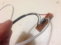
Here's a picture of the finished circuit, before I potted it to hell in hot-melt-glue and wrapped it in leccy-tape.

photo.JPG
 
Back
Top