Rodney64 said:No I leave the pack connected but trip my circuit breaker and yes charge though my balance leads.Offroader said:Rodney64 said:Quick question. I'm wanting to balance change using my BC168. I've been tripping the circuit breaker prior to changing but to trip the breaker I need to remove my side cover. Can I balance charge my pack when the controllers still powered up.
Rodney, how do you balance charge your pack? Do you connect into the balance leads and charge from there?
Without disconnecting your battery from the series connection, you would fry the balance wires if trying to parallel charge the pack.
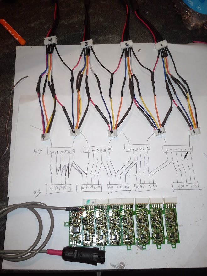
Rodney, I think you would need to somehow describe exactly how your battery pack is wired together. My battery pack is setup so that I have to disconnect three connections in order to balance charge.
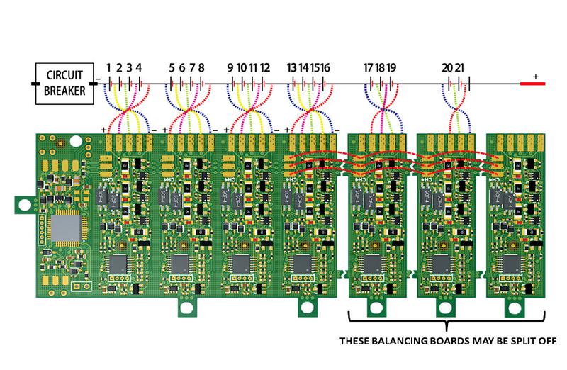
Simply by tripping the circuit breaker, which breaks one connection, wouldn't allow me to balance charge my 18s pack which has three 6s packs wired in series. The packs would still be wired in a series 6s-6s-6s for 18s.
If you are able to balance charge your pack by tripping just one circuit breaker than it probably shouldn't matter if your battery is hooked up to the controller or not. This assumes you are not running something like 6s & 6s for 12s and breaking the series with the circuit breaker.
You see charging wouldn't make any difference if you're still connected to your controller. It matters more when you plug your balance leads in and if you are trying to parallel charge.
I think someone in Australia custom made your pack? I would honestly ask him as he knows how your pack is wired together.