soldering hall effect sensors

fractal

1 kW
Joined
May 10, 2011
Messages
322
Hey guys, I'm about to install honeywell hall sensors on my motor. I have no experience with soldering but I have read and watched numerous videos on Youtube. I know that the iron needs to heat up the components first but how much? Those hall sensors are tiny and i'm afraid of frying them ! Can this happen? Any tips would be really great!
 
You can use alligator clips as heat sinks while you solder. Also tin your wire with solder before you mate the parts. The actually soldering action should only be for a second or two. Flux will help but probably not necessary. Should be easy to to.
 
You don't want to hold the soldering iron on the hall sensor to heat it up it will get too hot, the amount of solder you will need can be done by just quickly applying the solder iron to the solder on the spot. You won't need much solder to hold the hall leg to the wire.
 
I'm a clumsy solderer. The second time I did some halls, a wonderfull guy named Lyens agreed to sell me some halls with a short piece of wire already attached. Ahh, that was much easier.
 
snowranger said:
You can use alligator clips as heat sinks while you solder. Also tin your wire with solder before you mate the parts. The actually soldering action should only be for a second or two. Flux will help but probably not necessary. Should be easy to to.

Just wanted to add that the heat sink goes between the HALL and the point you are soldering at. Leave the HALL legs full length. Make the solder run on the wire first (tinning). Then with a little blob of solder on the iron, quickly touch it to the HALL and wire together. Put a piece of heat shrink over the bare leg and wire. Old hemostats make great heat sinks.
 
Thanks for the tips!!!
 
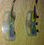
I'm also attempting to install some hall sensors and have been reading a lot of the threads for installing the sensors. Great work being done right now, but all the ones I have seen are skipping the early steps. I have looked up multiple outside of ES sources as well, and I haven't seen any mention of exactly how to wire up the halls. I'm talking about the wires going to the hall prongs themselves, not to the controller. In the "adding hall sensors to outrunners" thread, gwhy! posted this pic of his external mounts.
gwhy_hall wiring.jpg
This pic shows only one black and one red from each board, which has 3 halls on it. From the pic, you can't see the actual connection to the halls. Each hall needs to be connected to the red and to the black, correct? Would it be safe to assume that he tied each hall together with the red wire on the other side of the board, and did the same with the black? I'm planning on doing an internal mounting, so I'm guessing that I will have a red, a black, and a colored wire (either green, yellow, or blue) wire coming off from each hall sensor. And then when I bring them all together to exit the motor, I will tie all the red wires together into one lead wire, and the same with the black wires. So I will have 1 wire of each color (red, black, yellow, green, blue) coming out of the motor to the controller. Does it matter which prong the wires go to? Is one prong specifically for red and one specifically for black?
 
yes the polarity of the prongs is very important.

http://www.filur.net/PDF/Honeywell/kholla/SS441A.pdf

if you look at page 3 of this datasheet you can see the polarity of each prong.

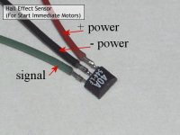
with the letters on the hall facing you, from left to right it will be + (red) / - (black) / signal (blue,yellow or green)
 
Thank you very much nieles, that was the info I just couldn't seem to find any where.
 
Jay64 said:
Each hall needs to be connected to the red and to the black, correct? Would it be safe to assume that he tied each hall together with the red wire on the other side of the board, and did the same with the black?

Correct. The red and black wires go to all of the hall sensors, so there has to be some traces on the back side of the board. The signal wires go to one sensor each. Here is a typical sensor connection:HallSensor.jpg
 
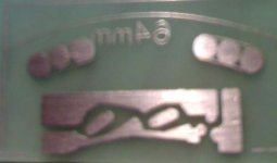
I just found a old pic of the boards this may help ( sorry its a bit blured ), this is the tracks under the board that you cant see on the other picture that Jay posted.
halls pcb small.jpg

The red and black wires go onto board on the left hand side of this picture.
 
Thanks guys, those pics really help a lot. Exactly the type of stuff I had been searching for. Now I feel a lot more confident to jump in and get these motors sensored up.

edit: One more thing. Looking at the wires coming out of my 24fet Lyen controller, the hall sensor wires are 22 awg. I'm assuming this would be the right size to attach to the halls as well. Is that a fair assumption?
 
nieles said:
with the letters on the hall facing you, from left to right it will be + (red) / - (black) / signal (blue,yellow or green)

Small problem. I just got my halls out, and there are no letters on them, no markings at all actually. I guess I'm going to set them up the same way that is in the pic by fechter, with the beveled side up and left to right like nieles mentioned.
 
Jay64 said:
nieles said:
with the letters on the hall facing you, from left to right it will be + (red) / - (black) / signal (blue,yellow or green)

Small problem. I just got my halls out, and there are no letters on them, no markings at all actually. I guess I'm going to set them up the same way that is in the pic by fechter, with the beveled side up and left to right like nieles mentioned.

Correct. A simple way to test your halls is with a 4-5V source across the power legs and a LED from the signal leg to the ground leg. Pass a magnet across the HALL and the LED will light. Pass the opposite pole of the magnet past the HALL and the LED will turn off. Now you can confirm your wiring and HALL.
You need to check the polarity on the LED first by putting it across the battery.
All of this wisdom from Arlo.
 
Jay64 said:
nieles said:
with the letters on the hall facing you, from left to right it will be + (red) / - (black) / signal (blue,yellow or green)

Small problem. I just got my halls out, and there are no letters on them, no markings at all actually. I guess I'm going to set them up the same way that is in the pic by fechter, with the beveled side up and left to right like nieles mentioned.

after I gave this some thought, I highly recommend you test them before going to all the trouble of installing them. No markings worries me a little. The price might also tell us more
 
Yeah, that is a great idea to check them before installing them. I got them from digikey or mouser, can't remember which at this point, so they should be the right ones.
 
But not so easy if you don't have one. :lol:
 
Beavinator said:
Easiest way to test halls is with a Lyen tester. Everyone should have one of those things! :mrgreen:

The tester is intended to check the Halls when they are in the bike. How would you test them, using the tester, before installing them in stator? The idea was to check them before going to the trouble of epoxying them in place and then having to remove a dud. Does this make sense?
 
If you're careful not to hook up the wires wrong, you can use a 9v battery or 5v power supply to power the sensor, then use an voltmeter on the output pin while passing a magnet near the sensor. You should see the output toggle when the magnet pole is changed. I forget which way is which, but if you aim the north pole of the magnet at the sensor you should get the opposite output when you aim the south pole at it.
 
Just to clarrify, you would put the voltmeter probs on the output pin (the signal leg?) and the neg power leg?
 
Jay64 said:
Just to clarrify, you would put the voltmeter probs on the output pin (the signal leg?) and the neg power leg?
Yes, but I do not recommend 9V, only 5V max for LED's. With a meter, you can go to the full voltage the HALL is able to handle.
 
testing them out of a circute is not so simple Jay,
you need to power the the sensor & i had to use a resistor to provide a load to get the hall to trigger with a magnet.

5v+ to the red wire, a small resitor on the black wire to the battery - & then your test probs will be + on the signal out of the sensor to ground...set the muti meter to match the voltage of your batteries (a pr of AA in a radio shack holder)& it should show you the sensor coming on & off with the magnet.

(i have nevered bothered with testing them before trial placing them in a motor....& its easyer to use the controller to power the halls anyway)
 
On of the biggest reasons I test my halls before installing them is because I could not find the specs on line which leg was what so I had to try a couple combos to get it sorted out. But It is so so so simple to hook power up to two legs and then the third leg will go from + to - or - to + as you pass a magnet of one polarity then sometimes it will stay if the magnet is strong enough, then you pass a magnet of the opposite polarity to turn it back. You can use a multimeter or a LED or almost anything that will show 0-5 volts or what voltage you are using. You can test from the output leg to the ground leg or the output to the positive leg remember its simply making the output go from low to hi and hi to low so either way will show you a signal if the magnet is the right polarity when it passes or touches the hall and if the polarity is wrong flip the magnet over and use the other side.

This is a simple 20 second test should not take you any longer to figure out! And this 20 seconds will save you wrecking you hall sensor when you have to chisel it out of the epoxy you install it with!!! :mrgreen:
 
Beavinator said:
Easiest way to test halls is with a Lyen tester. Everyone should have one of those things! :mrgreen:
How could it be more simple then this? [youtube]ZBj1YUNNuYM[/youtube]
 
Back
Top