F&P Motor Controller

zt3

10 mW
Joined
May 13, 2011
Messages
22
Is there any possibility that the Fisher and Paykel Motor Controller for Smart Drive Washing Machine be modified in such a way that the speed at 'Spin' mode could be controlled via potentiometer (instead of using switches to vary the speed)? I'm currently looking for a decent controller that could be used for the said machine but no luck here in our country. If ever there is a possibility, please do let me know. This would be our last resort for our project.

Thanks!

Nicko
 
search name "aussie jester" from memory he's running fp motor, its a standard 3 phase brushless motor, exactly same as hub motors, any hub motor controller will run it, you need rewire them in parallel though unless your going to be running at a couple of hundred volts, in parallel you can run 24v to 72v approx.
Alot of work, also you really need to change the magnets to neo type, they have ceramic mags, not much good!!
 
AFAIK, AJ isn't running any F&P motors; he's using RC motors.

There is a chap by the username of F&P here on ES that is using one, though, in a custom-built trike. Haven't seen him post in ages, though.
 
sorry my mistake, it will be fp username as you suggest
 
BTW, I checked the link given above for the australian forum, and that is the F&P guy's project, same as the ES thread (well, same project).
 
@ amberwolf: Do you happen to know what model of the 12 FET Infineon controller used by F&P guy? It seems quite difficult contacting him... Second, is this controller at http://endless-sphere.com/forums/viewtopic.php?f=9&t=27632 applicable to any brushless motor especially F&P motor (60S) wired in parallel?

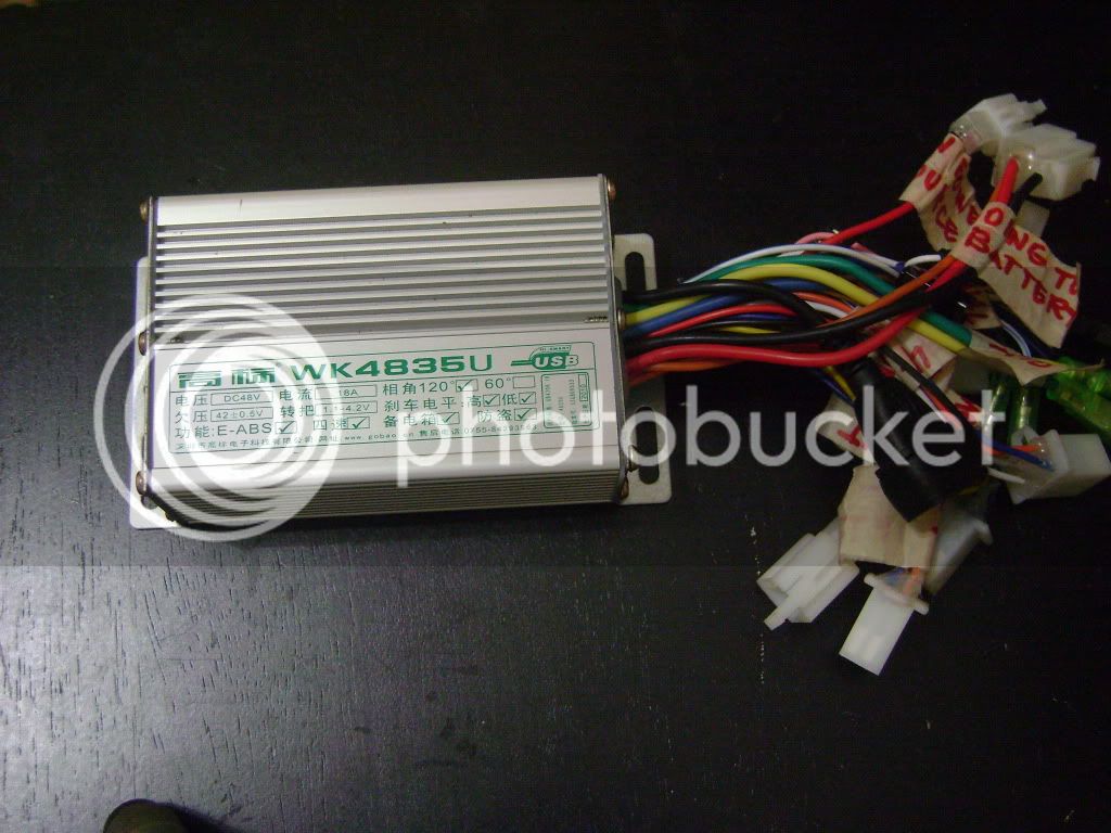
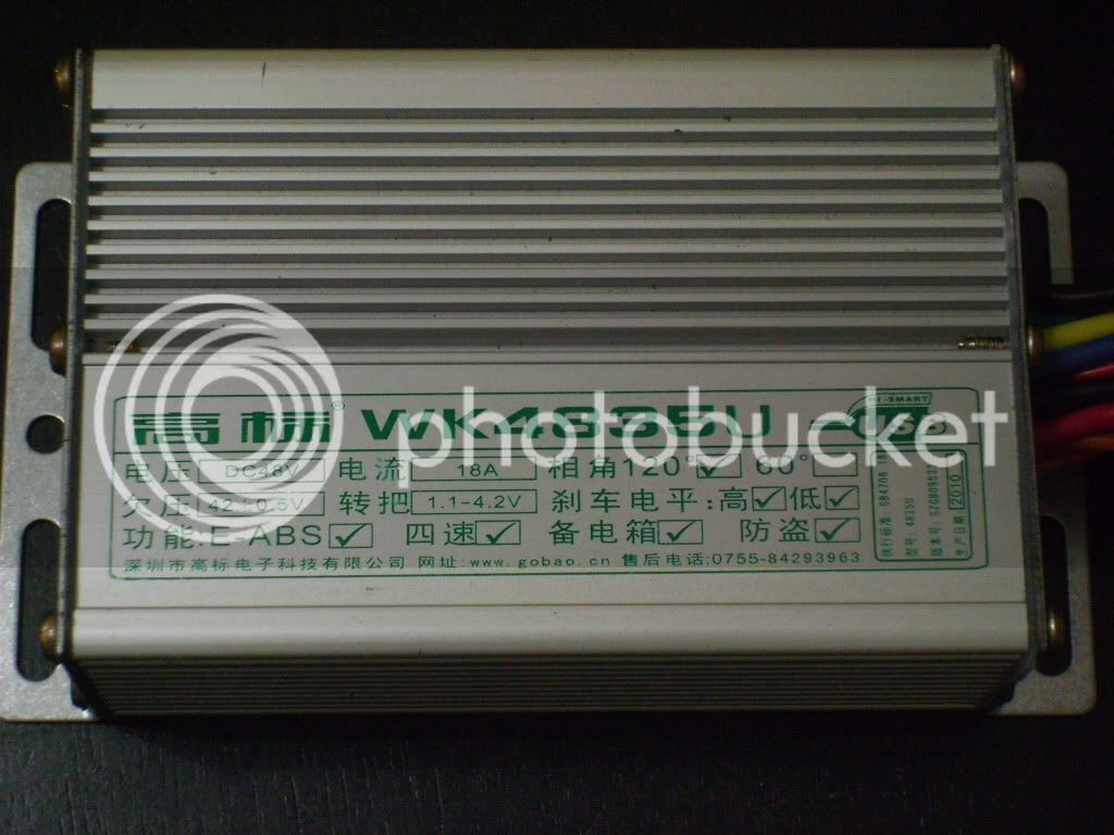
We recently bought a Chinese motor controller here in our country but when tested, the motor didn't rotate at all. After a few seconds, my group and I noticed something burnt up. We haven't checked yet what it was but we're guessing those were the three sensors. Also, when bought no schematic was provided except a wiring diagram. It also has a USB connection but no driver was provided. We opened the controller the other day and noticed 6 FETS embedded in the PCB. Is it just the controller or us having the fault?

Here are some pics:
DSC09970.jpg

DSC09971.jpg
 
Unfortunately I have no idea what he used, if it doesn't say in his threads. :(


BTW, I highly recommend creating a specific thread for troubleshooting your motor/controller issue, so more people will see it. Probably in Ebike Technical or Ebike General, where more people might lurk. ;)
 
that controller you used is 120degree
you need to check what the hall sensors are in the fp I cant remember off top of my head
check: all facing same way = 60degree
one hall upside down = 120degree
I would suggest change halls to ebike hall sensors, not sure if fp sensors are same output voltage as ebike halls, not all hall sensors are suitable for ebike controllers as output needs to be 1v to 4v
fp tried lots of controllers
if you go full throttle when testing and motor is not turning is bad idea can fry the fets ( have to be very gentle on throttle) also need to work out which is correct combo on the phase/hall wires
suggest try bmsbattery controller which can run sensorless or with halls, also it has pre learn function to make easy to match up hall and phase combination
 
Hi! Can I use this Kelly KBS72051,20A,24-72V BLDC Motor Speed Controller for Fisher and Paykel Motor?

oscthumb.php


KBS programmable BLDC motor controller provides efficient, smooth and quite controls for electric motorcycle, golf cart, go-cart, as well as industry motor speed or torque control. Motor speed controller uses high power MOSFET, PWM to achieve efficiency 99% in most cases. Powerful microprocessor brings in comprehensive and precise control to BLDC motor controllers. This programmable brushless motor controller also allows users to set parameters, conduct tests, and obtain diagnostic information quickly and easily.

Provide free male or female connectors matching with KBS controller.

Features:
• Intelligence with powerful microprocessor.
• Synchronous rectification, ultra low drop, fast PWM to achieve very high efficiency.
• Current limit and torque control.
• Battery current limiting available, doesn’t affect taking off performance.
• Low EMC.
• LED fault code helps user debugging.
• Battery protection: current cut back, shutdown and warning at high or low battery.
• Thermal enhanced rugged aluminum housing. Rugged connectors.
• Thermal protection: current cut back on low temperature and high temperature to protect battery and controller.
• Configurable 60-degree or 120-degree hall position sensor.
• Support any number of poles.
• Up to 40000 electric RPM. (Electric RPM = mechanical RPM * motor poles)
• Three modes of regen: brake switch regen, release throttle regen, 0-5V signal regen.
• High pedal protection: Disable operation if power up with non-zero throttle.
• Current multiplication: Take less current from battery, output more current to motor.
• Easy installation: 3-wire potentiometer will work.

General Specifications:
•Frequency of Operation: 16.6kHz.
•Standby Battery Current: < 1mA.
•5V Sensor Supply Current: 40mA.
•Supply Voltage: PWR, 18V to 90V for controllers rated equal or lower than 72V. 8V to 30V for 24V controller.
•Supply Current, PWR, 150mA.
•Operating Voltage, B+, 18V to 1.25*Nominal Voltage.
•Analog Brake and Throttle Input: 0-5 Volts. Can use 3-wire pot to produce 0-5V signal.
•Reverse Alarm, Main Contactor Coil Driver, Meter: <200mA.
•Full Power Operating Temperature Range: 0℃ to 50℃ (controller case temperature).
•Operating Temperature Range: -30℃ to 90℃, 100℃ shutdown (controller case temperature).
•Motor Current Limit, 1 minute: 50A.
•Motor Current Limit, continuous: 20A.
•Max Battery Current :Configurable.
 
Back
Top