GM Controller Capacitor Help

FastDemise

100 W
Joined
Aug 18, 2011
Messages
189
Location
Hillsboro, OR USA
I'm looking for advice about upgrading the capacitors on my Golden Motors controller.
Reading:
Low ESR Capacitors
http://endless-sphere.com/forums/viewtopic.php?f=30&t=22194&start=45

Novak Power Capacitor
http://www.teamnovak.com/tech_info/power_caps/power_caps.htm

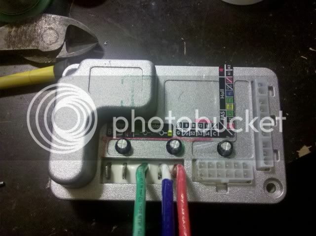
The reason I have become interested is I am currently running the controller right at it's maximum level. The electronics are rated to 63V and I'm running a 60V Li-Ion battery setup. I'm wanting to increase the life of this controller as it's serving my purpose just fine for college transportation. Reading forums of R/C ESC capacitor upgrades has me thinking it wouldn't hurt to just slap a couple 63V 1800µF capacitors I have on and be happy. But I understand that would perhaps give my ride a bit more punch it would not help in the slightest with the handling of the higher voltage I'm feeding it. I took a bunch of pictures as I had a hard time finding any of the golden motor controller so I'll share what I got.


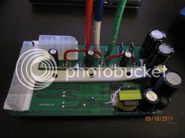
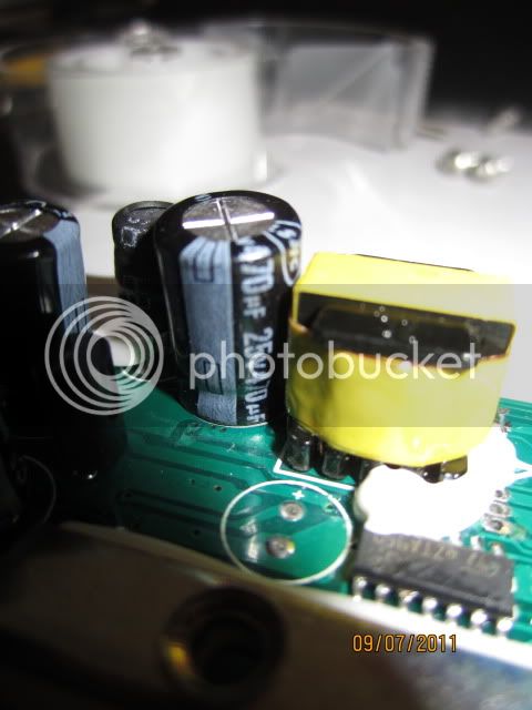
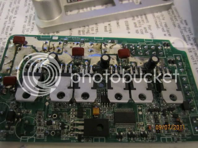
Now this is the controller. Nothing fancy, just wanted to show layout of the capacitors in question.
IMG_0189.jpg


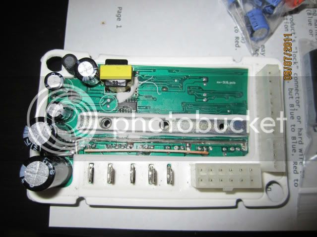
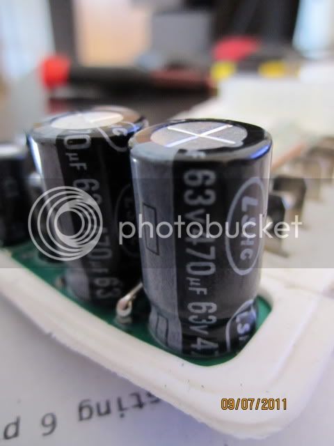
Now the 2 big capacitors are 63V 470µF
IMG_0180.jpg


The smaller right above 63v 47µF -->(Possible upgrade to a 100v 100µF??)
IMG_0186.jpg


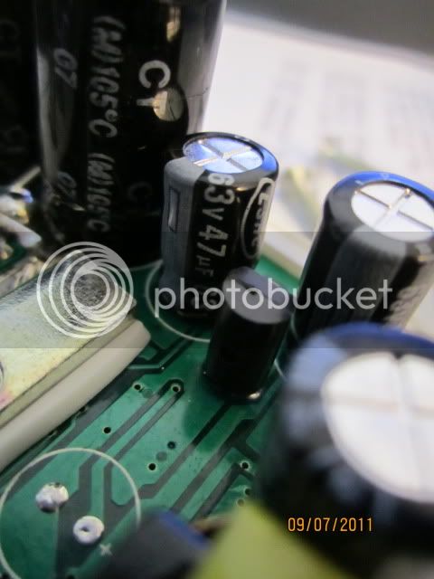
Just above that is a 63v 100µF -->(Possible upgrade to a 100v 100µF??)
IMG_0187.jpg


The last one is a 25V 470µF
IMG_0182.jpg


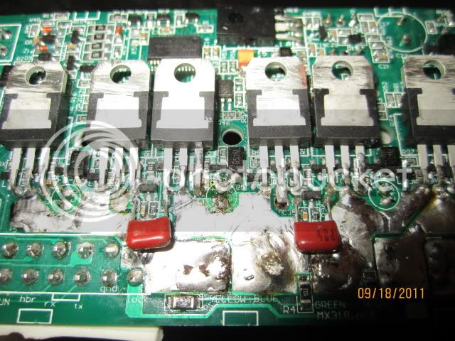
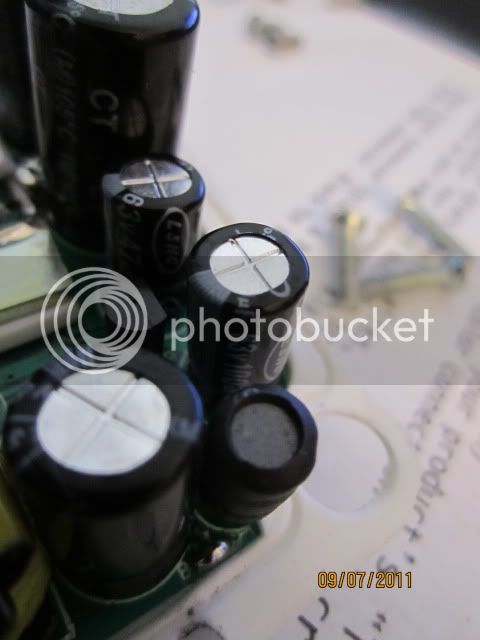
Upon looking at the board I've noticed 3 smaller capacitors on the underside that are showing some troublesome signs of overheating.
16v 47µF
IMG_0195.jpg

IMG_0196.jpg

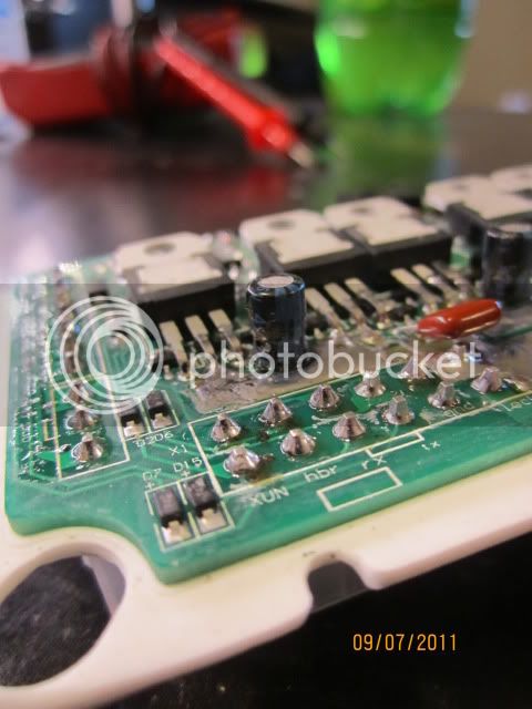
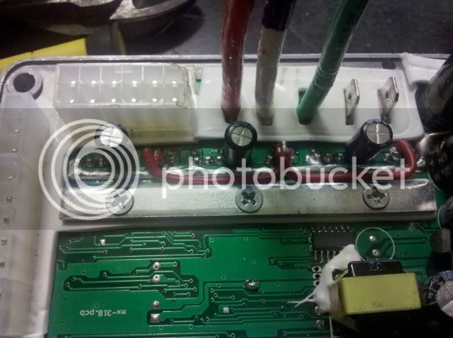
Don't know if it's good enough so I took another picture. The plastic seems to be slowly
IMG_0197.jpg


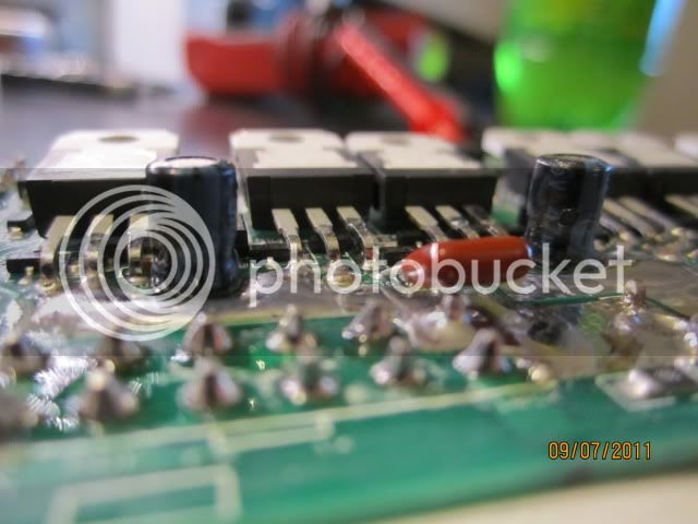
Now my first concern is can I easily just swap the tiny 16v for something with a higher voltage rating as long as I keep the capacity 47µF or higher??
If I replace my 2 main caps with ones of lower ESR I know they will have a very small µF rating. So can I offset that by attaching a small bank of x3 100V 470µF to the (+)(-) off the board and be okay??

I'm trying to be as specific as possible but please be easy on a novice electronic tinker.
 
16V is ok for those charge pumping caps. they carry current to the high side so the high side FETs will work. they work off the 15V supply.

if you have a 60V nominal lipo pack then the voltage is higher than 63V already. do you know how much voltage the output FETs will take?

have you measured the voltage on the 12V rail with your 60V lipo? did you do anything to bring down the input voltage to the regulators?

as you increase the voltage and capacity then the size increases a lot, and the leg spacing is also different for various sizes so keep that in mind when going through the spec sheets. i have some 100V1000uF caps if you need them, but not low ESR, just nichicon knockoffs.
 
Sorry, I should of been more specific. The battery I'm using is one I made myself from old batteries so fresh off charger it sits at ~59.9-60.1V.
I don't know what brands of capacitors are any good. I just grabbed a couple off the shelf of my local gizmo shop to see size difference and such. Guess I lucked out. x2 of the 100V 100µF capacitors I grabbed are Nichicon so those will be replacing the smaller 63V 47µF & 100µF as they fit perfectly on the board.
I'll connect it up and measure the 12V rail voltage for you.
 
So I swapped out the in bad shape 16v 47uF caps for 16V 100uF to better take the overheating issue. The mosfets are P140NF75 and a quick lookup is showing me they are good for 75V 120A.
 
It's back together with the 63V capacitors replaced with 100V. The controller didn't release smoke...yet...but I noticed the small yellow transformer now makes a much louder high pitch sound. Noticeable from about 10ft away. Nothing seems to be getting warm or hot while just being plugged and after I took the bike for a very short trip around the block only peaking to ~20mph. :D

dnmun I'm embarrassed to ask but where is the 12V rail?? I measured across the 2 thick bars on the top. (the silver and copper bar) and measured full battery voltage. :-(
 
It wouldn't be a bad idea to swap out the FET's with something like IRFB3077PBF... They should put off about 1/3 the heat as the stock ones. It just depends how much you care, and if you're willing to try it out. Its not exactly hard, but its not super simple. It looks like you can handle it, so its just a suggestion. Thats going to make a much bigger difference than the caps will.
 
Before I started replacing capacitors riding the bike to and from school keeping the cruise at 20mph the controller was never getting any worse than just warm to the touch from being stuffed in a bag under my seat. Right now heat isn't a issue with the setup surprisingly so I think that is telling me I can push the throttle harder without pedaling as much. :)
 
Just got it all back together and still no smoke *knock on wood* but I'm getting a very jittery throttle response from the motor now that gets worse with the harder I push the throttle. When cruising at a constant speed it's not very noticeable. Not smooth throttle anymore.

I replaced my charge pumping caps that were 16V 47uF that were showing signs of overheating with new 16V 100uF. and the 4 63V capacitors with 100V. I then did what I could to thicken up the leads on the board to help with power throughput.

I just pulled out the trusty digital multimeter and used the CAP setting to see if it worked. It read the small 100uF capacitors but the 470 and 1800uF were just reading OL. I'm curious that in buying my capacitors from a surplus gizmo shop I may have grabbed some shady parts. I'm under the impression a cap works or it doesn't. I'm just grabbing at excuses I think at this point. Any advice or guidance on where to point my solder iron or multimeter would be very appreciated.
 
My experience with this controller was that the jittery feeling you are getting is when the controller is getting too hot inside the wheel.....after longer distances it was more noticable.......in the end i just went with an external controller...so much less worry
 
I am using the external controller and the jittery feeling was from the instant it moved out of the garage. So from the initial test done just a few hours ago heat isn't my issue yet. :-( sadly can't ride it around long enough to test heat yet until I fix this 'jittery' thing. But thanks for your input. Pushing 60V in my 48V controller is sure to keep things hot so I'll know when I'm pushing the lil guy too hard. :)

I'm keeping an ear on recommended controllers here on ES when I either break this one or just feel like going faster.
 
Sadly I got far too over zealous and over heated the board basically ruining any chance of fixing it. hehe Well guess it's a test board to improve my solder skills on. :) I'll look at it that way at least. Now in the market for a descent 48V controller....Oh well pretty short lived thread. Thanks for the help anyway guys.
 
Well guess I spoke too soon. Spending a couple of days debating about some way of 'repairing' what I broke and amazingly I got it back up and running. The jittery motor was one of the 16v100uF capacitors being cut too short then being installed on the board so it wasn't making proper contact. I ended up removing the copper bar on the top of the board so I had room to install the 3 small capacitors on top. Then just used solid core 22ga wire. It isn't pretty and will require a bit of massaging of the top to make it all fix but preliminary tests with bike upside down have it working great.

IMG_0212.jpg


In the center you can see where I ended up scraping off some of the protective coat off the trace and just soldered it. The board just looks awful in the picture with all the flux everywhere. :-( The controller is only 4.5" long so the camera is real close to get the shot. I can't notice all that flux otherwise.
IMG_0209.jpg


Though not alot of activity on this specific topic, mostly due to it being Chinese Golden Motor stuff, this forum is a plethora of knowledge. You guys rock!
 
Just to show how I finished and setup my Golden Motor controller for my 60V battery setup. Real simple and everything fit. I would just caution using too hot a solder iron (45watt was too much for me) as you could melt the board and make things real hard on you. ^_^

I ended up redoing the wires so I could reinstall the cover. Just had to drill 3 7/16" holes to fit.
IMG_20110919_061221.jpg


Finished product.
IMG_20110919_061420.jpg
 
Back
Top