Kingfish
100 MW
Synopsis:
Create an ebraking scheme using two mechanical switches that will engage ebrake and brake light together. The ebrake operates at 5VDC max with the switch in-line to pull the signal up or down depending on the controller circuitry. The brake light is a 12V LED taillight having three wires: Taillight (running light), brake light, and GND.
The design methodology for my Brake Lever is as follows:
With that given, I took a common left-side bicycle hand brake lever and attached two SPDT Switches (Without Roller), stacked one on top of the other. Switch can be purchased from RadioShack or any other electronics supply house.

The Switch. Qty-2
To affect the modification, we need the brake lever assembly, two switches (or one if not incorporating the brake light), and an object that will be mounted to the lever-part of the brake that will hit against the switch when the brake is closed (disengaged).
Originally I used superglue to hold all these items down in place, but eventually it will fail. The preferred method that withstood the rigors of being On The Road was discovered by trial and error, and eventually fell upon using fasteners; two small 4-40 UNC 2A screws, or the smallest metric will do as well, about 5/8 or ¾ inch long. The screw should fit tightly into the hole without damaging the packaging.
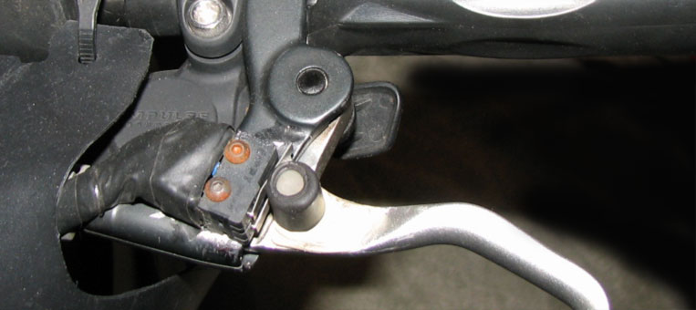
Brake disengaged. Screws are rusted; hard to find stainless in that size.
I took one switch and made a template from a sheet of paper (Post-it note works great); poke out the two holes, cut out the shape, and place it on the body of the brake assembly where the switch will go. Use the holes as a guide for drilling. Make the holes slightly smaller than the mounting screw. The screws will tap into the soft aluminum without too much effort, though it should be a snug-fit.
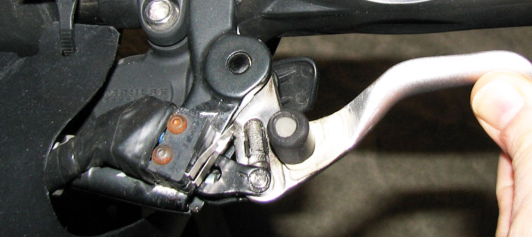
Brake engaged.
Test-mount your switches with the screws, and tighten down until just before the screws impact the brake lever, and note the excess. File the length down to match-fit: Enough to go through the aluminum but not rub against the lever. The two screws will do a great job of holding it into place! :wink:
Create a post that will impinge against the lever-arms of the switches. I used an old plastic part and superglued it down, but a bolt will work just as well. I didn’t get the placement exactly right, so there are two ways to adjust: Add more layers to the post (heatshrink works well) and/or bend the metal arms out until contact is sufficient. Small note: I filed away at the lever to create a good solid fit for the post; do what you need to do to make it right")
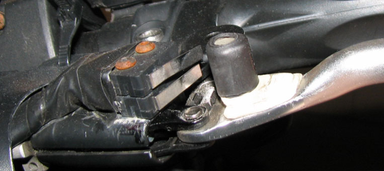
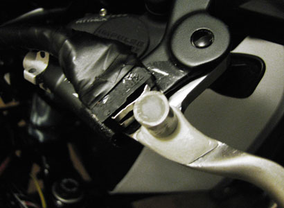
Brake: close-up of the post.
Next we wire it up. Remove the switches from the brake assembly. Decide if your ebrake operates when the switch is N/O or N/C. Mine works when the switch is N/C which is the same for the brake light. Example: No hands on the brake, no ebraking, and no brake light. When I pull the lever, the switch goes to a N/C state and completes the circuit, ebraking begins, the brake light comes on, and eventually – if I pull hard enough the mechanical brakes will engage.
Place heatshrink on your wires before you solder them into place (sounds simple but I forgot twice). If using both switches, use the screws to hold them both together and wrap electrical tap (or heatshink) around the entire wire-side of the assembly to unify it. Mount the switches to the brake. Test, test again, be finicky – make sure it works to your satisfaction, and be happy. Wiring up the rest should be straight-forward.
This is how I made mine work, and it is still functioning today. Word of caution: Don’t use clamps to hold the switches in place because they are fragile and will break without giving the slightest indication of failure.
Thanks where thanks deserved goes to Dnmum and Farfle for their hospitality and use of tools in Portland and Bend. 8)
ADDENDUMS:
Related posts Reed Switch buggered, and OtR: The Day of Gremlins!
Cheers, KF
Create an ebraking scheme using two mechanical switches that will engage ebrake and brake light together. The ebrake operates at 5VDC max with the switch in-line to pull the signal up or down depending on the controller circuitry. The brake light is a 12V LED taillight having three wires: Taillight (running light), brake light, and GND.
The design methodology for my Brake Lever is as follows:
- Desire to eliminate Hall Effect issues that use field-effect for make-break circuitry
- Facilitate positive reliable mechanical switching for ebrake
- Facilitate a second mechanical switch for the new LED taillight/brake light
With that given, I took a common left-side bicycle hand brake lever and attached two SPDT Switches (Without Roller), stacked one on top of the other. Switch can be purchased from RadioShack or any other electronics supply house.
The Switch. Qty-2
To affect the modification, we need the brake lever assembly, two switches (or one if not incorporating the brake light), and an object that will be mounted to the lever-part of the brake that will hit against the switch when the brake is closed (disengaged).
Originally I used superglue to hold all these items down in place, but eventually it will fail. The preferred method that withstood the rigors of being On The Road was discovered by trial and error, and eventually fell upon using fasteners; two small 4-40 UNC 2A screws, or the smallest metric will do as well, about 5/8 or ¾ inch long. The screw should fit tightly into the hole without damaging the packaging.
Brake disengaged. Screws are rusted; hard to find stainless in that size.
I took one switch and made a template from a sheet of paper (Post-it note works great); poke out the two holes, cut out the shape, and place it on the body of the brake assembly where the switch will go. Use the holes as a guide for drilling. Make the holes slightly smaller than the mounting screw. The screws will tap into the soft aluminum without too much effort, though it should be a snug-fit.
Brake engaged.
Test-mount your switches with the screws, and tighten down until just before the screws impact the brake lever, and note the excess. File the length down to match-fit: Enough to go through the aluminum but not rub against the lever. The two screws will do a great job of holding it into place! :wink:
Create a post that will impinge against the lever-arms of the switches. I used an old plastic part and superglued it down, but a bolt will work just as well. I didn’t get the placement exactly right, so there are two ways to adjust: Add more layers to the post (heatshrink works well) and/or bend the metal arms out until contact is sufficient. Small note: I filed away at the lever to create a good solid fit for the post; do what you need to do to make it right
Brake: close-up of the post.
Next we wire it up. Remove the switches from the brake assembly. Decide if your ebrake operates when the switch is N/O or N/C. Mine works when the switch is N/C which is the same for the brake light. Example: No hands on the brake, no ebraking, and no brake light. When I pull the lever, the switch goes to a N/C state and completes the circuit, ebraking begins, the brake light comes on, and eventually – if I pull hard enough the mechanical brakes will engage.
Place heatshrink on your wires before you solder them into place (sounds simple but I forgot twice). If using both switches, use the screws to hold them both together and wrap electrical tap (or heatshink) around the entire wire-side of the assembly to unify it. Mount the switches to the brake. Test, test again, be finicky – make sure it works to your satisfaction, and be happy. Wiring up the rest should be straight-forward.
This is how I made mine work, and it is still functioning today. Word of caution: Don’t use clamps to hold the switches in place because they are fragile and will break without giving the slightest indication of failure.
Thanks where thanks deserved goes to Dnmum and Farfle for their hospitality and use of tools in Portland and Bend. 8)
ADDENDUMS:
Related posts Reed Switch buggered, and OtR: The Day of Gremlins!
Cheers, KF