Meanwell 48v problem - FIXED !!!!

Ypedal

Moderator
Staff member
Joined
Dec 27, 2006
Messages
12,530
Location
Moncton NB, Canada
I got this used from a forum member, the fine folks at the postal service have decided they would do their thing and it has arrived DOA... argh.

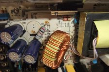
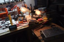
So.. this is what i got.
48v-mw-problem1.JPG

No stickers but has AC wired and DC out + and -..

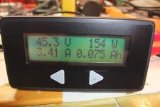
plug the sucker in, fan comes on, no output. :(

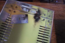
So i opened it up, had a look, i am a TOTAL electronics dummy so ... yeah.. i'm admitting that right now.. :oops:

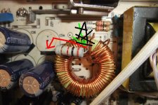
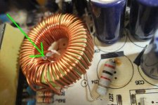
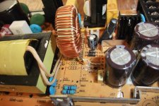
I found this yellow ring covered in copper coil thing bobbing around loosely in there.. and one resistor that was not connected to anything, so.. since they looked like they would fit.. i solderd A with B.

48v-mw-problem2.JPG
no joy yet.

the LED on the front of the unit will not light either. but the fan does turn.

Anyone ?

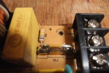
( and yes, i noticed there is a solid wire where a fuse usually goes... got it like that, an acceptable practice in my shop so i figure if it worked like this before shipping, should still work now.. so ruling that out .. ?? )
 
I have NFI why that resistor would be there, but the toriod (yellow thing with wires) is used to filter the output from the power supply - if it is open circuit (should be between the output of the shottky diode and capacitors) then there will be no output from the supply.

Have a look at the meanwell schematics for more information.
 
yup the torroid goes to the board. the resestor goes to the board too. i had some like that . silicone was too cheap .......did u try mabye the 240/120 switch? i had one that would only output 50v max even with mods. turns out i had it on 240v,,,,
 
switch is indeed on the 115v setting, made sure of that.

remove resistor from round yellow thing, check.. easy .

Looking closely at the board.. i see a potential candidate .. see red arrow.. there is a remnant of something sticking out thru the board there..

safe to give it a try ?
 

Attachments

  • 48v-mw-problem3.JPG
    48v-mw-problem3.JPG
    59.1 KB · Views: 1,321
ok.. so turns out my 100v , 2 unit charger, has an identical unit so i pulled a few screws and took a picture of the insides..

up skirt shot :
48v-mw-problem5.JPG

So, the toroid thing goes upright, and when i do this to the dead unit the white goo ( dont know what it's called.. but like a foam/epoxy ashesive to keep bigger parts in place.. ) pattern matches up to an upright mounting.

no clue where that resistor goes, but will sleep on it and maybe wake up with a spark of ideas..

We really need to start a Meanwell Master List of how to's in the wiki.
 
ok.. took it completely appart, i'm fairly sure the resistor goes to the red line instead of the capacitor spot i got it on now..

and the toroid thingamabob, by shining a flashlight thru the board, looks like i can pick any available hole here and it all connects to the back copper area..
 
Cha Ching !

Damn i love it when i " fix " something and it end up working ! ( I got plenty of experience on the failure end of things.. )

Could not get the parts thru the holes in the board, i tried to unplug them with the iron but no go.. i dont have a solder sucker yet ( hitting up ebay as soon as i'm done typing this ) so i cut open a piece of power wire and took some strands, twisted as many as i could fit thru the hole while the pad was liquid from the iron.. then soldered the parts to that.. and cut the excess off the back.

cleaned the " Fet ? " thermal paste and applied a fresh layer ( very thinly ) .. plugged it in with fingers crossed and WHAM.. we go green light and 45.5v output !

Now.. to apply a load and see if it holds up... :eek:
 

Attachments

  • 48v-mw-problem-fixed.JPG
    48v-mw-problem-fixed.JPG
    53.9 KB · Views: 1,279
Seems kind of redundant when there is the LED across the output as well ~ would drain the caps down to the Vf of the LED (about 2V or so)
 
I just found this thread. If that's the meanwell that you got from me, it used to belong to icecube57 so maybe he added the resistor. I vaguely remember him saying that he'd hotrodded it in some way but can't remember exactly. I used it a few weeks ago and didn't have any issues though and there was definitely nothing bouncing around inside. It sucks that the post office was rough on it. I'm really glad that you got it working.

I'd recommend hot gluing the torroid back in place if you didn't already because it might shake loose again if you haven't. You could also PM icecube57 and see if he remembers what he did to it and why. I looked through my PM's and there's no info on the power supply and ice deleted his posts in the sale thread.
 
One little quick tip too. If you're ever doing a repair like that again and are having problems getting a component through a hole on the board, or getting the solder out, a little drill bit makes life easy. I don't even use a drill. I just wrap electrical tape around the shank of the bit until it has a little handle and I spin it with my fingers. I get more precise control that way. Just an FYI. :wink:
 
This is indeed that unit !

I'll pm ice and see what he can recall, i plan to series this with another 48v unit to bulk charge 100v on my KMX trike, any idea what this this will output ? ( amps. ) before limiting ?

I thought about the drill bit idea, then hesitated as some boards are multi layered ( i dont think this one is.. but am kinda clueless about these things.. so fly by seat of pants totally applies lol )
 
I don't know much about the meanwells but if I remember right, it was putting out 6-7 amps at 50v. I had a few of them and charge controllers for them but since I got a hyperion 1420 that I run off of the batteries on my solar array, I didn't ever do much with the meanwells other than power the hyperion at 24v 5A occasionally and use them as bench power supplies for controller testing after repairs and other little experiments. Ice used that power supply in series with another one to charge his 66v pack so he'll have a lot better info.
 
The only thing i did was change the current limit and capped it at 9-10A and increased the voltage range to 17-53 ... those damn coils always get broke in the fcking mail. I had two supplies DOA when i ordered them off ebay thats what made me give up modding meanwells cause i can keep getting broke shit and deal with the people on ebay for 1 week trying to replace them or get a refund. That loose resisor i have no idea whee it goes i didnt put anything that huge in there i used like some 1w or less for the current mod... my resistor mod is on the bottom side of the board. my blue pot should be over by the led.
 
use rtv silicone to hold the coil on the board . same stuff for valve cover gaskets. u know :wink:

Heres what i do .

buy meanwell for 35$ shipped off ebay.
take out board. snip zd1 under big transformer to raise voltage limit.
short fan transistor to on.
solder in 10k trim pot in place of vr1.
rtv any loose parts
use dremel on shunt get 6.9 amps. any more will kill it. u gotta grind it right down!!

now i got a nice 20-63v 6.9amp charger
 
I got a S-350-12V from Sure Electronics 2 years ago. Arrived not working and they sent me a replacement for free. It just buzzed and hissed and didn't have any low voltage.

Well you inspired me to pull it out of my parts bin and attempt a repair on my old MW.

I probed around on the HV stuff without any luck till I touched the main transformer pins.
Turns out they were cold solder joints. Quick reflow with a solder iron and the little green LED came on for the first time, the thing works absolutely perfectly.

I think I let out a little woot myself.
Well done Ypedal.

Also found this site has great info in it http://www.repairfaq.org/sam/smpsfaq.htm
 
More MeanWell fun !..

Different unit( Not the same as ealier one pictured ) .

-------

Upon opening up, found loose toroid bouncing around in there.. so that was first clue.. 2nd was the fuse on the AC side was blown..

so.. drilled thru the board ( thx for that tip ! ) .. and soldered in a few legs to work from..
 

Attachments

  • MW-repair1.JPG
    MW-repair1.JPG
    58.5 KB · Views: 1,023
ok.. so time for a test.. no clue if i can power this up safely without installing it in it's box so i bolt it in... now.... last time i did this i seem to recall a grey rubber membrane thing between the 2 large Fet looking things and the case... but since this thing has been sitting on my desk in pieces for a week or more... nuts and bolts are scattered.. and that membrane thing is MIA..

Having no clue if this is " absolutely needed " or not... i figure, screw it.. probably dont need it.

so.. i plug this baby in and POW.. the whole office goes dark ! :shock:

damit....

so i head to the basement.. reset the breaker.. turn the lights back on and take MW no.2 apart for inspection..

and what da ya know.. i find that grey membrane !!!!!
 

Attachments

  • MW-repair3.JPG
    MW-repair3.JPG
    39.8 KB · Views: 1,022
Back
Top