Motor Hall Sensor and Harness Replacement

Knuckles

10 kW
Joined
May 2, 2008
Messages
971
Location
Wrong Island, NY
CHAPTER 1: CHECK SENSORS AND OPEN THE MOTOR

OK. So your motor is DEAD! Bummer. But fixing it ain't so bad. First test the hall sensors just to be sure.
If your sensors don't vary from 0V to 5V they need to be replaced. See Hall Sensor Testing vid ...

[youtube]7m8DA6mmo84[/youtube]

Heck you may want to beef up the phase wires while your at it.
So here is our patient ... The infamous "Black" Grubee motor ...
GEDC0170.JPG
Open it up ...
GEDC0171.JPG
You may have to pry the cover off ...
View attachment 2
Opened at last ...
GEDC0173.JPG
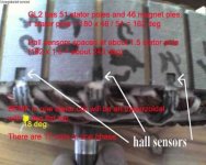
Closeup of the magnets (rotor) ...
GEDC0174.JPG
Closeups of the coils (stator) ...
http://98.131.176.65/endless-sphere/GEDC0175.JPG
http://98.131.176.65/endless-sphere/GEDC0176.JPG
Pry the other cover off ... http://98.131.176.65/endless-sphere/GEDC0177.JPG
 
CHAPTER 2: REPLACE THE PHASE WIRES

Here is the existing wire (green) and the new 14 gauge replacement.
View attachment 2 high res pic here ... http://98.131.176.65/endless-sphere/GEDC0179.JPG

All three new 14-gauge phase wires thru the axle.
GEDC0180.JPG high res pic here ... http://98.131.176.65/endless-sphere/GEDC0180.JPG

The new phase wire (green) now soldered to the windings.
high res pic here ... http://98.131.176.65/endless-sphere/GEDC0181.JPG
more soldering here ... http://98.131.176.65/endless-sphere/GEDC0182.JPG
all new phase wires solder complete ... http://98.131.176.65/endless-sphere/GEDC0183.JPG
 
CHAPTER 3: PREPARE THE HALL SENSORS

Here are the hall sensors. Tiny little beggars.
GEDC0185.JPG high res pic here ... http://98.131.176.65/endless-sphere/GEDC0185.JPG

The patient on the operating table ... http://98.131.176.65/endless-sphere/GEDC0186.JPG

And here is the motor with the "dead" sensors.
GEDC0187.JPG http://98.131.176.65/endless-sphere/GEDC0187.JPG

After chiseling out the old sensors, check that the new sensors fit nice.
GEDC0188.JPG http://98.131.176.65/endless-sphere/GEDC0188.JPG

Now it's time to solder some wires to those tiny little sensors.
GEDC0189.JPG http://98.131.176.65/endless-sphere/GEDC0189.JPG

Hey ... That was fast! (NOT).
GEDC0190.JPG http://98.131.176.65/endless-sphere/GEDC0190.JPG
 
CHAPTER 4: INSTALL THE HALL SENSORS

Here are the hall sensors wrapped with electrical tape.
View attachment 3 http://98.131.176.65/endless-sphere/GEDC0191.JPG

And more pics of wiring the hall wires into the harness inside the motor.
http://98.131.176.65/endless-sphere/GEDC0192.JPG
http://98.131.176.65/endless-sphere/GEDC0193.JPG

I prefer super glue to set the sensors (some guys like the Gorilla).
View attachment 2 http://98.131.176.65/endless-sphere/GEDC0194.JPG

OK. Sensors are glued into place. So far so good.
View attachment 1 http://98.131.176.65/endless-sphere/GEDC0195.JPG

Now just a little twist tie to keep things neat and secure inside the motor.
GEDC0196.JPG http://98.131.176.65/endless-sphere/GEDC0196.JPG

Onward ...
 
CHAPTER 5: FINISH UP THE NEW WIRE HARNESS

Boy this sure looks messy! Let's clean it up.
If you look closely you can see I spliced together the original thin phase wires and the new 14-gauge wires.
GEDC0197.JPG http://98.131.176.65/endless-sphere/GEDC0197.JPG

Also make sure the cover will fit over the new harness.
GEDC0198.JPG http://98.131.176.65/endless-sphere/GEDC0198.JPG

And in true fechter-The7 style I numbered the stator poles and magnet pairs.
View attachment 1 http://98.131.176.65/endless-sphere/GEDC0199.JPG
GEDC0200.JPG http://98.131.176.65167/endless-sphere/GEDC0200.JPG

So now just put it all together. I like electrical tape.
http://98.131.176.65/endless-sphere/GEDC0201.JPG
http://98.131.176.65/endless-sphere/GEDC0202.JPG
http://98.131.176.65/endless-sphere/GEDC0203.JPG

Test Time!
 
CHAPTER 6: INSTALLATION AND TESTING

I use two 36V SLA chargers is series as an 88V power supply unit (PSU) for no-load testing.
This works perfect for my controllers and DD brushless motors.

See no-load test video here ...
[youtube]WkPE3DaqbV8[/youtube]

Ready to hit the road!
GEDC0206.JPG http://98.131.176.65/endless-sphere/GEDC0206.JPG

cheers
 
CHAPTER 7: ROAD REVIEW

THIS E BIKE IS SICK. Way too fast!

That new harness (new 14-gauge phase wires) makes a BIG difference. MUCH POWER! Motor ran just slightly warm.
a123 bats ran warm too. Harness was ICE cold. Crazy controller was mildly warm (never got hot at all).
I actually wiped out a few times! Yikes! It's a freak'n Buck'n Bronco! Easy Girl! Daddy loves you!
FN Wild Stallion! FNA!

[youtube]nydDj7pvqWU[/youtube]
I so crazy! :shock:

HA HA HA! I love my CHOPPER!
:twisted: :twisted: :twisted: :twisted: :evil: :twisted: :evil: :twisted: :evil: :roll: :shock:
GEDC0213.JPG http://98.131.176.65/endless-sphere/GEDC0213.JPG
 
Very informative!

Your DD motor looks very similar to GL2 hub motor.
According to solarbbq2003, this motor has performance between Crystalyte 4000 and 5000.

The7 said:
GL2 Hub Motor (solarbbq2003)

1) It has 51 stator poles and 46 magnet poles (23 pole-pairs).
This gives 51/46 stator poles per magnet pole (180 deg).
1 stator pole = 180 x 46 /51 deg = 162 deg
There are 17 stator coils in one phase

2) Hall sensors spaced about 1.5 stator poles with one only one at the gap between poles.
Spacing = 162 x 1.5 deg = about 243 deg (say 240 deg).
Then spacing becomes -240 deg : 0 deg : 240 deg.
-240 deg is equivalent to 120 deg.

3) The stator poles are not skewed.
So the back EMF in one stator coil is trapezoidal with a flat top of 18 deg.

4) The resultant phase BEMF will NOT be 17 times of (3) even if the 17 stator coils are connected in series.
Instead the resultant phase BEMF is very close to an sine wave (more sinusoidal the MAC-BMC 600W).

5) The Hall signal could be configured as –81 deg, -39 deg, 39 deg and 81 deg with respect to the phase BEMF. (Maybe it is also as –18 deg and 18 deg). But there is no 0 deg.

6) It is Y-connected, the resultant phase to phase BEMF is about 1.732 of (4). There will be a further 30 deg advance when compared with (4).

7) With the symmetrical location of Hall sensors, there is no difference in performance in forward and reverse running.
 

Attachments

  • gl2 winding and hall sensors.jpg
    gl2 winding and hall sensors.jpg
    35.5 KB · Views: 13,480
The7 = "One Lit Dude" (ie his propeller cap is spinning at Mach speed)!

And this is a good thing. Thanks to you, The7.

cheers
 
Wow! Lung island still has nice spots on it! Havent been back to the city since '87. Interesting motor, but not geared???? Makes a good deal of noise for a plain vanilla hub, huh!
otherDoc
 
I like it, wonder how it runs on 48 volts.

Thanks for the vids and pics "knuckles"
 
I was wondering how to test my hall sensors. It's still not clear to me even though I'd read a few posts on it. I have a nine volt battery. I have a multi-meter. I have a, disassembled, motor. I have new hall sensors(possibly bought prematurely) Is there a way to test them in this state or do i have to reassemble the motor. I like how your meter probes just stick in the connector and stay. I was thinking I needed four or more hands to do this.
 
If the motor is apart, you can use a loose magnet to activate the hall sensors manually. With the halls powered by your 9v battery, and enough extra hands to keep the meter probes attached, place a magnet up to the hall sensor and check the output. Reverse the magnet polarity and check again.

To avoid needing too many extra appendages, I use short pieces of small gauge copper wire twisted around the meter probe and the other end is small enough to jam into the connector.

Be very careful not to short the hall signal lines to the battery positive, as this could blow the sensor.
 
dscn0125pr0.jpg


So in order to power the sensors with the 9v I tried to connect the negative and possitive of the battery to the negtive and positive of the XLR connector. I put a small piece of cardboard ripped off of a box of Tylenol cold and sinus to put in between the pins going to the red and black wires and the others. I attached a wire to the black probe on the meter and twisted it around the wire coming from the negative on the 9v. Now, what I want to do is touch the red probe from the multimeter to one of the sensor pins and wave the hide-a-key box, which is my magnate, over the sensors to try and get a change on the meter which is set on dc 20v. I noticed the battery was quite warm and thought maybe the possitive and negitive wires were touching in the connector. I tried putting another small piece of cardboard into the connector to keep these separate. I have been unable to get this working so far. I'm thinking it might be easier to get a female side xlr connector and set it up for testing. Am I on the right track?
 
You have the right idea, but if the battery is getting warm, something is shorted out or the battery is reversed. You need to be very careful not to short the battery to the signal wires or it can blow the hall sensors if they are not already blown.

Those little XLR connectors really suck for testing.
 
having the mating connector makes it much easier to do the tests. i made up a little board with the connectors, battery and a few led's to show the hall sensors switching as i turned the motor.

HALL TESTER-1.jpg

HALL TESTER.jpg

the led's show when one of the sensors is activated. i have both the male and female connectors for the mini XLR and the JST connectors. this is also very useful when i want to test controllers that use one connector and the only motor i have on hand uses the other.

rick
 

Attachments

  • HALL TESTER.pdf
    10.1 KB · Views: 249
Dude, you beat me to it. I was designing the same kind of thing.
Mine is cheaper though. This attaches to the motor to test the hall signals coming from the motor.
Hall Sensor Tester.jpg
 
Do these breadboards come with cheese?
 
So I finally got a result on this hall effect sensor test. I sent ebike.ca an order for a female xlr connector to test with and got an email back from Zev suggesting I just unscrew the back of the connector and test there. I had already unscrewed the back but everything was under heat shrink tubing. So I was thinking the heat shrink is not there always and is an extra added thing that's not necessary. I wrote back saying this and Justin responded that I could slide the heat shrink up or test at the controller. Here's a pic of what I ended up with.

dscn0130fu0.jpg


Now, the results were curious. I expected two types of results one for working and one not. I got three. The green wired sensor is clearly bad reading almost nothing and not changing. The yellow wire sensor changes from about 8.5 to 7.5 when I run the magnate over it. The blue wire sensor read 8.5 to .5 when I trip it with the magnate. So do I have one bad sensor or two?
 
Parker said:
......... The green wired sensor is clearly bad reading almost nothing and not changing. The yellow wire sensor changes from about 8.5 to 7.5 when I run the magnate over it. The blue wire sensor read 8.5 to .5 when I trip it with the magnate. So do I have one bad sensor or two?

From the above readings you have one good sensor- Blue; the other two are bad, but in different ways.

d
 
I got one of the bad sensors out. I don't have a heat gun so I tried to heat it with a propane torch. I was so cautious with it that I didn't heat it much though. I started using one of my sharp chisels but when i sliced through a tiny bit of insulation on the black wire and a sliver of copper I switched over to a beater chisel. I noticed that in the 'when good drop outs go bad' thread in the basics section and this thread the hall sensors are first attached to little wires then to the long wires going from the controllers. So I'm thinking I need some little black/red/colored little wires. Could I just find these at home depot or radio shack? I was thinking of soldering them onto the wires at the stator but I will probably have a hard enough time doing it with wires not connected to anything so no need for further complications.
 
See my post here for halls ... http://endless-sphere.com/forums/viewtopic.php?f=2&t=4464
See my post here for hall replacement method ... http://endless-sphere.com/forums/viewtopic.php?f=2&t=4626#p68476

Ha Ha ... Keywin is my own private digikey ... I have SH*T LOADS of neato stuff now !!! :D

stuff.jpg
 
Knuckles,

good to see that you believe in a balanced lifestyle. personally i cannot balnce without a coffee in one hand and a cigarette in the other. though it does get tougher as the cigarette burns down.

i guess Coors is an okay substitute for coffee, but personally i prefer a locally brewed Canadian or Molsons if only for the higher alcohol content.

rick
 
here is how it looks in action:

n_101.jpg
n_102.jpg
n_103.jpg
n_104.jpg
n_105.jpg

sorry i missed step #6 but it would show Hall #3 and Hall #1 lit.

and with the motor running all 3 are on pretty much all of the time. the first red LED is for power.
n_100.jpg

the circuit sort of evolved a bit. to keep the led at a constant brightness regardless of supply voltage each LED has its own 5mA constant current supply built from LM317's. i also added a battery and a couple of diodes. this way the led's and halls can be powered by the controller or the battery for stand alone motor tests.

i also added the screw terminal strips so i can hook up other motors, or feed the hall outputs to a frequency counter.

rick
 
Back
Top