Constant Voltage Pedal Generator

h0tr0d

1 kW
Joined
Apr 28, 2012
Messages
460
Hey guys!

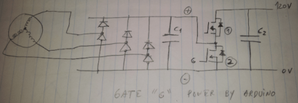
I would like to make a generator out of a brushless motor for my ebike (chainless transmission)

I need:
- Constant voltage to charge the battery @ 120V, independent of rpm
- a control knob to vary the the torque on the pedals (current control?)
- 100W constant, 500W peak

I have a C80-100, thinking in winding it with 15 turn 14awg (already have both) giving a kv of 40 plus a 4.5:1 reduction (540rpm max generator, ~13.5v)

There are some threads here about generator but constant voltage I haven't seen...

Help out Please!! :mrgreen:

Edit: some numbers.
 
If it proves necessary, a kv of 5 is possible with 120 turns(!!) of 23awg wire. https://www.wires.co.uk/acatalog/SX_0300_0710.html
Estimated 6750uH inductance.
 
Hum... http://en.wikipedia.org/wiki/Boost_converter
Looking at Wiki and after NJay explanation over the phone, NOW I get what he meant about not needing a "typical" DC DC converter, since I already have a big coil (inductor) in the motor.

Anyone wants to help with the calcs for this little project?
 
Yes, the windings of the motor can be used as the inductor for a boost converter. Basically you short out the motor windings with a FET bank and a diode circulates the output to the battery when the FET switch opens. This is the same arrangement used for regenerative braking. The 'short' is applied and released at a high frequency and you control the torque by changing the duty cycle of the on time. In the crudest form, all you need is a PWM circuit driving the FET gates and a big diode. You also need a 12v supply to run the PWM circuit, which could be taken from the output. The 12v supply doesn't need much current, just a few milliamps. The output voltage will be clamped by the batteries and should work over a very wide range.
 
Is this circuit correct?

To limit the current I have to put a shunt, right?

Thanks Fechter!
 

Attachments

  • ForumRunner_20130504_201931.png
    ForumRunner_20130504_201931.png
    87.3 KB · Views: 1,987
That's basically it, although I don't think you need C2 and I have doubts about C1 being needed too.
You will also want to drive the top MOSFET (with a complementary signal from the bottom one plus a small dead time) or connect together its gate and source for it to work as a diode; it can be replaced for a better and cheaper diode (schottky) if the current is not very high.

A shunt or current sensor has to be added to monitor the current and act on the PWM duty accordingly, like a resistive shunt before the 0V exit to the battery.

Arduino can only provide 5V, which will turn the MOSFET on but not "very ON"; you must have a 12V rail in your system and 2 resistors 1 cap and 1 transistor solve the problem.
 
Some calcs are definitely needed...

http://www.ladyada.net/library/diyboostcalc.html
http://www.ti.com/lit/an/slva372b/slva372b.pdf
http://services.eng.uts.edu.au/~venkat/pe_html/ch07s3/ch07s3p1.htm

Freq: 20 khz
Min volt in: 2.7 (24 rpm legs)
Max volt in: 13.5 (120 rpm legs)
Min volt out: 118
Max volt out: 119
I out: 4.2 (max for 500 W)
V ripple: 1V
Cranks: 170mm
Reduction: 4.5


1- Motor power rating= for 500 W @ 13.5 V = ~37 A mean. But energy will go to the battery in pulses, I'll have peaks of 74 A in the motor and schottky.
2- kv 40 = 0.24Nm/A = 9Nm; 40Nm @pedals (23.5kg force)
 
what size/type of battery are you going to use ?


personally, I'd just use a normal motor and a 3 phase rectifier feeding into your battery pack

ignore voltage limits etc.. you won't be able to pedal hard enough to push too much current into them...

iirc 200watts constant is about right for most peoples 'leg power' when pedalling...

Olympic sprinters can spring at about 2.5kw

so if you're super fit, and can pedal @ 500watts constant, that's only 10amps at 48v...


that, and keep a volt and amp meter on the handlebars :)
 
My battery:
35S A123, 119V max.
http://endless-sphere.com/forums/viewtopic.php?f=2&t=48980#p722703

I'm trying to build an e-bike, not e-motorcycle. Since I will pedal at any speed, because I want to, might as well serve for something.
Very small effect in charging? Agreed but the work here developed will serve for chainless drives for others to use, recumbents with 3km chains, etc.

A normal motor and a 3 phase rectifier will NO resistance until the the motor voltage equals the battery voltage. Spinning on air until "X"rpms and then huge force... not for me.
 
h0tr0d said:
A normal motor and a 3 phase rectifier will NO resistance until the the motor voltage equals the battery voltage. Spinning on air until "X"rpms and then huge force... not for me.


you just need to wire the motor for the right rpm for your battery voltage so revs=close to what you pedal at
 
knighty said:
you just need to wire the motor for the right rpm for your battery voltage so revs=close to what you pedal at

That's the easy but not very effective way of doing a generator. If it was for a combustion engine, always operating at peak efficiency, no doubt I'd do it that way.
But I need to pedal really slow or fast, with a lot of force or no effort at all. That's a too wide rpm range to properly do without some electronics...

"Things should be as simple as possible but not simpler" Uncle Albert One Stone. :mrgreen:
 
Why not just use that pedal power to propel the bike forward?

Way more efficient than generating current to charge a battery that then drives a motor to propel the bike forward. Cut out the middle man.

And if you're pedalling you'd save more battery than you could charge anyway.
 
With ranging from 0 to 150kmh, how many gears would I need?

Efficiency, agreed.
 
And space for that chain and multiple reduction stages is very difficult to find...
 
Back
Top