Heaters and Filaments 12V RMS Regulator

Alan B

100 GW
Joined
Sep 11, 2010
Messages
7,809
Location
San Francisco Bay Area, USA
For some time I've considered making a regulator to provide DC to my electric heated vest from the bike battery. It wants to see 12 volts (at about 50 watts), but a heating element doesn't care if the value is AC, DC, or pulsating DC. So a complex switching regulator with big heavy inductors and filter caps to produce clean DC is not needed. We have used this technique for incandescent filament voltage regulation as well (many postings on CandlePower Forums).

So I combined a couple of my designs and did a quick board layout.

heater%2520reguator.png


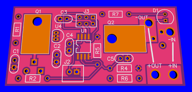
It should handle up to about 10 amps at ebike voltages. For a heated vest (or other heated items) it can be set up to produce different RMS voltage settings for different heat outputs. There is a pushbutton input for selecting different levels, turning on/off, etc. For lighting such as running a motorcycle incandescent headlight it would be set to produce fixed 12-13V RMS. Those draw 60-100 watts so are in range of this regulator. Board is about 1.2 by 2.5 inches.

Here is the similar setup I made to fit in D M@gLite flashlights and handle mega-bulbs for high powered hotwires (up to about 12-15 amps) a few years ago. It is the same diameter as a "D" cell battery, to give an idea of the scale.:

mag%2520d%2520hotwire%2520regulator.png


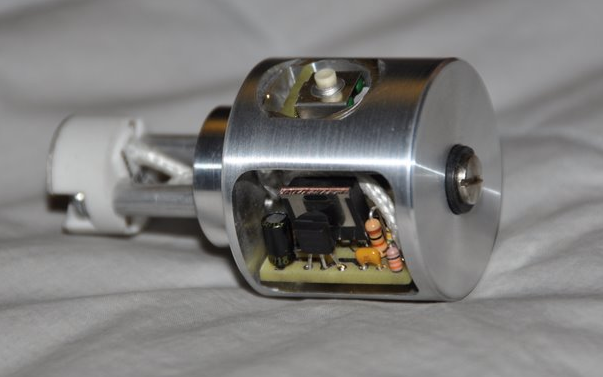
So this approach saves bulk, weight and power as compared to the standard approach of a DC-DC converter, and it avoids a second battery and the attendant monitoring and charging of that approach.
 
For folks using regular off-the-shelf motorcycle heated garb (vest, pants, gloves, insoles) a temperature controller is (usually) a must. Some of the standard controllers are very nice and the general notion is to put it in an inside chest pocket or small belt-bag and run the reduced-power Y-harnesses from there (single power wire pair goes waist to bike). Somewhat less popular is an in-bike mount with a bars-mounted control and one or two wire pairs running to the waist for clothing power. (I have a wireless control unit myself...)

You proposal is interesting, but these units would not be useful with the stock 12v controllers which would exclude all the folks needing them, so I think you would want accommodate/incorporate that functionality - perhaps add pads for an external pot to give limited range adjustment 0 to the preset max provided by the base unit (presumably PWM). This would allow a normal chassis pot/knob to be put on the box with the unit (in-pocket use) or remotely mounted on the bars for in-bike installation.

Your design may already be able to trivially address this with a series fixed resistor - but in the absence of a schematic to see what you have in mind - here's the functional requirement :D

EDIT - actually, a power adjust of maybe 30-100% is probably enough....
 
I don't use a controller/regulator/thermostat with my motorcycle eVest. Never have in the nearly 20 years running it. Years and years of regulating it manually via a big rocker switch I've come to conclusion a simple regulator like Alan's showing would be plenty for me. The best part would be operating off the traction battery without all the extra dc-dc convertor stuff..
 
Ykick said:
I don't use a controller/regulator/thermostat with my motorcycle eVest. Never have in the nearly 20 years running it. Years and years of regulating it manually via a big rocker switch I've come to conclusion a simple regulator like Alan's showing would be plenty for me.

Certainly not all heating products, outside temperatures, exertion, and personal taste run the same. My gear absolutely needs regulation and a brief scan of reviews of contemporary products shows the discomfort of folks who have tried getting by without it.

Alan is looking to make a product, so a small addition to address a larger user audience may be desirable. In your case - no need to wire up the pot. Easy....
 
My vest has a several level setting control, but I would just bypass it and go directly to the vest, it just plugs in series so easy to remove it. It would be easy enough to have a pot compatible input, at the moment I have a pushbutton input there but adding a supply pin and setting it up for a pot would be easy. Of course one could always just turn it on/off periodically with a switch as suggested. I appreciate the suggestions and comments. The behavior of a regulator like this is dependent on the software, so more than one flavor is possible. We might even make the software open so folks could customize it to their needs.

A version for running filament headlights would just have a fixed voltage output. The pushbutton could be omitted, or it could be an on/off control that would be memorized. Or a light sensor might be used to make it automatic, or perhaps that's too much to bother with.

A fuse is needed for safety, haven't decided how to handle that. If the FET shorts and full voltage is applied to the vest it would be important to quickly pop a fuse, and that should work well since the current would jump by a factor of 6 on an 18S ebike. The solid state fuses don't have a high enough voltage and current rating, and for best protection the fuse should be determined by the rating of the load. For example on my 4 amp vest I would probably fuse it for about 5 amps. It would be used on cold weather which tends to raise the trip level of the fuse, so no need to fuse a lot higher than required.

The schematic of this is fairly simple, some of the complexity is due to generating microprocessor power from the high battery voltage. Most of the complexity is in the software to do the RMS regulation calculations. Since I already have those from a previous project it would not be hard to adapt them here.

This is not my highest priority project, but it has been something that I have considered since I got the vest, and it may tie in well to a halogen headlight that I'm considering to improve the after dark commute. That would take a separate copy of the board from the vest with different software, but these are small. They should not generate much heat, most of it will probably come from the regulator to power the micro. I'm looking at a switcher for that instead, but the complexity and cost go up, not clear it is worth it. Partly that depends on how low I can get the power consumption of the micro, which may be quite low.
 
Since this would run halogen headlights just fine, if it could output enough current (at least 10-12A) it would be great for my bikes' present car headlight systems. Do you think it would handle that, run off a ~60V peak traction pack? (or could be modified to do so, easily enough?)


I don't know if the HID systems out there require regulated DC or if they'd run on AC/chopped DC, but if they would then that would be nice, too.
 
The primary issue will be the current related heating, 10-15 amps is where one FET limits out with minimal heatsinking (two in parallel would help that). 60 volts should be no problem. We'll have to build some and test them to see precisely where they start getting hot, but there's a good chance that 12 amps is going to work, especially if good enough FETs are used.

Depending on what I do for headlights I might try building some of these in the not too distant future.

The HID and LED lights need clean DC, so this is not going to suit them. It is a good shortcut for filament bulbs and heating elements.
 
Well, as long as all the parts are thru-hole I could be a guineapig for building a test unit. :) I don't think I can hold an iron steady enough to do any SMT parts anymore, though. :(

I didn't see a circuit diagram/schematic--what's the chip, U1? If it's available in a DIP or SIP part I could probably put wires on it and run those to the various points on the board the leads go to, as long as there's no issue with inductance or something by doing that.
 
No updates?

I have limited knowledge for electronics but would it not be simpler and easier to build it with a Arduino?

Please review my idea:

E-bike batterie ~80V

A zener diode 1N5338B with 85 ohm resistor gives the Arduino mini PRO the 5V from the 80V batterie.
The Arduino is programed to switch a Irfp4110pbf on and off with the 5V from the zener on the gate.
The Heater gets 80V only a short time from the Irfp4110pbf and the timing can be set with a potentiometer on the Arduino for the desired temperature.
 
The microprocessor I've used for this project is a Tiny45, which is a bit too small to run Arduino code. You could use an Arduino, it would just be somewhat more costly. The Tiny45 costs about $1 and is an 8 pin chip. So it is smaller and cheaper than a Mini Pro (and draws somewhat less power). But a Mini Pro should be able to do the job. It is a pretty simple project either way, it is just slightly different hardware.
I've built a bunch of these for flashlight regulators. Thus far I haven't built one for the ebike.
 
Mini Pro i get for $4. Two for $6.49 shipped

But could it work as i described ?
Is the 5V from the 1N5338B enough to switch the Irfp4110pbf ?
Is 1x Irfp4110pbf enough for a ~80w heater?
 
5V on the gate is a bit marginal. You might want to go with a logic level gate part. We've gone way beyond 80W with my flashlight setup.

You have to determine the peak current you need for the micro etc and then draw that much all the time plus a little through the resistor. The zener will take what the micro doesn't use, as long as it is within the Zener's capacity. Watch out for the resistor heat in this application. The regulator I've used won't go to 80V, so I put a pre-regulator on it. More complicated than a resistor/zener though. If the Arduino draws 25mA then the resistor needs to dissipate almost 2 watts. That would be a 3K resistor.

If you used an 85 ohm resistor to a 5V zener the resistor dissipation would be E^2/R = (80-5)^2/85 = 66 watts!! Choose your resistor carefully!
 
I will try it first with the 5.6V 1N5339B zener . Absolute maximum for regulated V on Arduino is 6V.
I have read that a Arduino UNO with disabled PWR LED and L LED only 7mA uses. So the Mini without USB bus some less.

What will the potentiometer and the Irfp4110pbf in action consume if its happy with the 5.6V?

Thanks for clarification with the resistor i will try it than with a 2W 3k assuming 25mA is enough for the complete regulator.
 
Note that if your current drain momentarily exceeds 25mA (or whatever current you set your resistor for) that your Arduino will crash without a good regulation system. You should feed the Arduino 8-9V and probably include a capacitor across the zener to store some energy. That will give it some headroom and make it more likely to keep running.
 
Back
Top