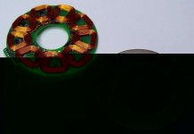
DIY electric motors

Joined
Dec 3, 2018
Messages
34
Hi!

What a nice forum, so much interesting stuff to read!

Is there anyone else around here who is trying to design/build electric motors intended for electric bicycles?

I have spend allot of my free time constructing different motor designs with varying results during the past year.
I have now finally achived a brake trough in my latest design wich i have mounted on a full suspension MTB.
Mechanically it is reallay quite simple, using the old friction drive wich, by the way, works supprisingly well, at least for my non-mud use. So far my speed record on flat surface is 41km/h.
At this time the friction drive acually seams to withstand driving on both wet alsfalt as well as wet gravel-road.
Not that i dont think hub motors and such are superior though... But so much harder to build the DIY-way.

It would really be intressting to hear about other entusiast experience on the DIY electric motor topics, both the successful versions as well as the hmm...less... successful...

/Axel
 
I haven't seen much in the way of friction drive around here. I tried it on my first few attempts and couldn't find the line of traction VS heat. I then just bolted a plane outrunner into a gearbox.

Welcome!!
 
Thank you johnrobholmes,

I hope the pictures shows up properly.
The friction wheel is 60mm diam, 2½" i belive. Made of plywood... The friction material = emerly paper for now, is not in place.
I guess i was lucky with the aligning/tension part, no troubble with heat etc.
Yes, the motor is water cooled.
Maximum power depends on how fast the cooling water pump is running... :D
Havent been able to heat it up more then 50degres C so far, and that was without circulation pump, only the water inside the motor (1/20 litre) in combinbation with the surface area of the motor to cool it down...
View attachment 1
View attachment 3.jpg
View attachment 4.jpg
View attachment 2.jpg
 
No actual machining work is neded, you just need a desent pillar drill and a electric hack-saw. But yes, i have done all parts of this motor myself.
Controller, well, its really simple but still hard to explain... i have built a simple 555-IC PWM unit wich was originally intende to run a computer fan or just to dim LED:s. The frequency was about 200Hz. I switched one capacitor to raise the frequence to 10.000Hz, 10kHz, to avoid self induced interferenc.
The PWM unit flickers the sensors wich in turn flickers the HEX FET transistors, sort of....

At the moment i am waiting for the batteries i have ordered to arrive, i intend to run the motor on 72volt. My current set up is 48v.

Pancake? Yes it is quite slim. I think about it as a sandwich or a hamburger motor since it has to rotating slices, magnetic discs, one on each side of the stator. :D
 
axbor22 said:
Havent been able to heat it up more then 50degres C so far

Then you haven't been running it hard enough. :p

Considered building a simple dyno to get some power/efficiency numbers?
 
Really cool project, Axel!

I assume it is a brushless design, right? - What controller are you using, or home made?

What kind of power do you get out of it (what kind of ride does it give I mean here), for what kind of input power?

Are the coils bare, or do you use iron laminations to concentrate the magnetics? They almost look like bare loops! This would mean a high speed design...
 
Hello all!

Yes it is brushless, a two pole motor (does not self start, not a problem in this setup), 20 permanentmagnets on each side of 20 electomagnets.
Controll system: a pure home brew based oppon to super cheep photo diodes, so fast switching, we are talking nano seconds!
You are right ZapPat it is a air-core motor, no iron in the stator= no eddy curents an no hysterises losses and low weight... :D
It is actually not a very high rpm motor 900rpm/12 volt, 3600rpm no load @ 48 volt. This is with 0.25mm copper wire in the electromagnets
in combination with thick, 8mm, N42 permanet magnets. Weaken the perm mag or use a thicker copper wire and you will get a really high rpm motor and vice versa.
The motor is actually quite torqey. Friction roll 60mm on a 26" wheel gives a 11:1 reduction.
Effeciency is at best closer to 80 then 70% wich is so odd concerning the not optimal shape of the magnets and the relatively huge airgap betwen the to magnet carrying rotor discs, upp to 16mm. A nother really bad thing is that it is driven by a square wave ac wich is less efficient than a sinus shaped one.
However, it is simple to build this kind of motor to work with ordinary RC-hobby ESC. But the ESC are so expensive. But they are also morefficient, sinus wave generating i belive.

I have not yet reached the moitors max Ampere-limit, still waiting for more batteries to arrive.
Im just about to connect a silent computer coler to my water cooling system so i hope to be able to really push trough large amount of A whit out start boiling water inside the motor.
 
axbor22 said:
However, it is simple to build this kind of motor to work with ordinary RC-hobby ESC. But the ESC are so expensive. But they are also morefficient, sinus wave generating i belive.

Sine waveform controllers are pretty rare in the RC world - most use block commutation, I think.
 
Miles said:
axbor22 said:
However, it is simple to build this kind of motor to work with ordinary RC-hobby ESC. But the ESC are so expensive. But they are also morefficient, sinus wave generating i belive.

Sine waveform controllers are pretty rare in the RC world - most use block commutation, I think.

Here's an exception: http://www.sinusleistungssteller.de/index.html

I am aiming towards the softer sine wave commutation approach myself, since the torque ripple I get with a direct-drive hub motor (mostly during acceleration) annoys me a bit. An ebike accelerating should feel smoother in my opinion!

By the way, I have been wondering for quite a while now why my 3 years old direct drive golden motor hub has skewed poles, like this:
Inside a golden motor DD hub (or crystalyte) - Skewed poles.jpg
The diagonal skew of the poles is exactly the width of one pole from one side of the stator to the other.

Would this be to reduce torque ripple?
Wouldn't it lower efficiency somewhat, since the magnet's poles can't ever totaly be over the electromagnet's "sweet spot"?

Thanks for anyone offering info about this!
 
Hi ZapPat,

Right me if i am wrong, but i think the twisted stator is shaped that way to minimizet the "cogging" effect motors with permanentmagnets and iron core coils usualy have.

Regarding sinus-wave vs trapetzoid vs square-wave ac, my point is that the testmotor i made, 3 phase AC-delta wound-sensorless, to match redy-made ECS:s were slightly more efficient than my 2-pole motors with home-brew controller. The motor itself is even simpler to build than my 2-pole photodiode sensored motor, but more expensive due to the cost of the ESC. The 3 phase AC-delta wound-sensorless version could also be wound with thicker 0.5-0.7mm copper wire with less heat developed in the coils (obviusly making the motor mor efficient) without becomming a very high rpm motor.
 
That's pretty cool.

Skewed poles are there to reduce torque ripple. Yes, they do detract slightly from the maximum pull, but that loss is offset by the reduction in torque ripple, which also causes losses. It's mainly to make it smoother at low speeds.

axbor22, I think you may want to look at changing the rotor/stator pole configuration to give it a more 'conventional' 3 phase arrangement. This will allow self starting and most likely improve efficiency. A more typical arrangement would have an even number of magnet poles and a multiple of 3 stator poles. Getting the gap closer will help too. Optimum gap in most motors is 1-2mm (between the magnets and the coils in your case).

I like how you have magnets on both sides to close the flux path. You could improve things even more if the coils were 'flat spiral' configured, so there is minimal empty space in the center, and at the same time thinner so the two rotors are closer to each other.

Another idea might be to use ferrite or powdered iron cores in the center of each coil. While this will introduce some core loss, using the right material will make this minimal. This would greatly increase the torque constant and allow for fewer turns of heavier wire.

The magnet backing plates look pretty thin. I'd guess the flux in these plates is more than enough to saturate the metal, which will reduce flux. When the metal is thick enough to avoid saturation, you can put a nail or something magnetic near the outside and it will barely attract. If the plates are saturated, then the nail will attract strongly to the outside. Just guessing, I'd think you'd want a backing plate that is nearly 1/4" thick behind the magnets. The thick part only needs to go behind where the magnets are, so it could be a fairly narrow ring. Low carbon or silicon steel is the the best material for this.

If you want to avoid needing the heavy iron, you could also consider a Hallbach array for the magnets. This would be challenging to build but would reduce overall thickness. Stronger N50 magnets are available these days too.

What kind of current does it draw at no load, full speed?
 
Hi fechter,

Thank you for the interesting comments.

My no 1 priority with this motor project is simplicity, DIY-ability, hence the choice of design.
3-phase motors are simple to build, i have made a couple of them already but designing matching controllers is currently not within my intellectual range.
With an even numbers of permanent and electromagnet-poles like my design, 20-20, iron core is not an option since the rotor would have a extreme cogging effect and, worst of all, would be locked in the dead-timing position.
Yes the rotor discs are thin, only 1.5mm. I have made several out of 0.9mm sheet steel as well, all for the simplicity of manufacturing.
So they are "leaking" magnetism out back. So far not really a problem though.
On the other hand, the flywheel effect created by a heavier rotor would probably smoothen out the motors aggressive 2-pole nature. Hmm...
I like the low weight to, so there are several things to take under consideration here.

Distance between magnets and coils are 1-2mm. The stator is 12mm thick, and again, for the DIY-simplicity i allow a air gap of 2mm on each side to not demand to much precision skills of the builder. So 16mm total gap between the magnets. In a iron core motor the space between the permanent magnets does not matter much since the iron core transfer the magnetic flux so very well between the opposing magnet poles, but in this case, i think not only the air gap between the coil and magnet, but also the total distance does matter.

The simple circular coils are much easier to make and disc magnets are the cheapest to buy.
I have made motors with coils which had what would apper to be a more efficient shape, but i could not detect a increase in efficiency.
I am considering ordering magnets of similar size but with N52 magnetization strength. This would give me more torque, but also lower rpm at any given voltage, and i am not sure if i want to go beyond 72volt.

This motor consumes 1.1A @48 volt no-load.
 
Simple controller...
Here is the complete setup except for the PWM circuit, wich replaces the AA-cell in the picture.
With the AA cell the motor only have a on-off function, which is ok for power levels up to 200W, above that you will kill the HEX FET transistor at startupp without PWM.
View attachment 6.jpg
View attachment 5.jpg
 
So you use optoelectronics instead of regular hall sensors for faster response for timing? I had noticed in one hall sensor data sheet that is comonly used in brushless motors that the response delay time was 4us, which could make for some loss of efficiency at high speeds.

Your 1.1A no load current sounds pretty darn good! What kind of power can this thing handle anyways?? 500W continous, 1kW, ...? Can you climb hills OK with it?

I just noticed that ebikes.ca has some new hub motors, with greater diameter and thinner profile, they look really sweet! If you could build your motor into something similar, that would be too cool! It's the way to go I think... I can imagine a motor that would be just as big as the bike wheel itself, no more spokes at all, for some serious power and efficiency!

Nine Continent hub motors at ebikes.ca

If I had an unwanted and working 3 phase motor controller hanging around here I would be tempted to send you it just to see you build and test your motor in a 3 phase configuration!
 
Well, quite frankly, i started out with photo-transistors; they have about 15micro seconds raise/fall time which worked well for slow rotational devices. Later on i just stumbled across the photo diodes which have a raise/fall time around 6nano seconds, which put you in the insane position of contemplating the speed of lights effect in long wires connecting the sensors...300mm wire "delays" the signal 1 nano second....
I have not tested Hall Effect sensors and I do not know anything about them. They must be good since they are so common.

I would be disappointed if the motor handles less then 1kW.

Regarding Hub motors.
I have built 2 of them. Long story short: I built them premature of my knowledge accumulation.
I will probably give it a third try in the future. :D
But i want to sort the friction-roll-motor out really thoroughly first!

A cupple of hub pictures, many, many poles....in vain....

View attachment 7.jpg
View attachment 8.jpg
View attachment 1
View attachment 10.jpg
 
WOW! SuperCool! I was planning on make my own motor too, but I suck in making things. OTOH, I'm very good at electronics... You can't have it all! :lol:
I like a lot the motor with a thousand magnets!
 
Take a look at this motor...
The coils are designed to be quite flat and the active sections are at 90 degrees to the magnet rotation. The magnet is a solid ring that has the poles magnetized into it. If your diameter was large relative to the magnet size, you could use rectangular magnets and remain near optimal. You can see the hall sensors in the middle of three of the coils.

A long time ago on the old Voltage Forum, there was a guy in Sweden named Honk that was making his own ironless motor that was similar. He used multilayer printed circuit boards to make the coils. Each layer was a flat spiral and the layers were connected by through plated holes and soldered connecting wires. He used separate magnets on the rotors which had a solid iron backing. His design had multiple rotors and stators (6 or 8 as I recall) that were stacked up.
Axial ironless axial motor.jpg
 
fetcher, that motor reminds me old floppy disk drives... But as I remember it, the magnet is a single one, and the coils were switched in opposite pairs leaving the other coils unpowered. But the motor you posted has 9 coils, so maybe it works another way.
 
The pancake motor above has 9 coils, so each phase would have 3 of the coils. These are commutated in the standard six step brushless sequence.
 
Congrats Axel on your great little pancake. I was really taken with such a simple compact design although a real novice about such motors, but I am very interested in what you have built and the application.
A friction roller can be a very good way to drive a bike - I made up a clipon with a 25cc ICE three years ago and it worked a real treat, even went quite well on a wet road but no good on hills of course. The noise and blue smoke got me thinking about electrics and a couple of years ago I managed to get hold of a brand new front wheel hub conversion kit which has been just great. Highly recommended for trips about the suburbs etc etc and even into the city at non-peak times. (I am 73yrs and 75kg but had not ridden a cycle for over 50 years but get a lot of fun from my trusty e-mtb.)
Now about your great pancake: I've had a good dekko at the pix and would really appreciate a few details regarding the specs and mounting of the magnets and coils - and also the discs. I've spent quite a lot of time checking out ebikes and motors on the net but have only found your DIY project as giving any details at all about construction.
I've got reasonable workshop skills but know only a little about electronics. Any help you've got time to offer would be highly valued. I'd love to have a go at your design as a w/shop project.
 
I hope you don't object to my "brainstorming" philosophy of throwing out ideas that may be zany but could spark creative thoughts in others (that's how ES works, isn't it :) ). But...
I'm thinking: Could you use defunct CD/DVD plastic discs as the basis of a motor? You could make them stronger by glueing several together and you could perhaps embed magnets into them with a little heat? Or just glue magnets and coils to them? Or embed them by drilling into them with a large drill bit/small keyhole saw?
What do you think?
 
This is a very interesting thread you have Axel :)

How are you progressing with your motors ? cause we are all ready for your diy build instructions..... ha ha.

Jocko I am similar to you with better workshop skills that electrical, with mechanicals things you can try it and see what happens, electrical is like..... woops that make a spark, I wonder if that fried it.

I found a wind turbine construction built that might help others like me, get there head around how a motor like this is built.

View attachment turbine kit.pdf

It came from this site:
http://www.windstuffnow.com/main/builders_corner.htm

View attachment turbine-2.png


Axel I am not sure if you know this but there is a Electric Motor Design and Construction section at the http://www.rcgroups.com forums, there is a guy making a motor to fit inside the wheel of a Kick Scooter, you might find it interesting:
http://www.rcgroups.com/forums/showthread.php?t=997243

Dean.
 
Back
Top