Chinese Battery....hmmmm, with Pictures!

barbs00

100 W
Joined
Jun 1, 2017
Messages
107
Location
Australia....mate! (Gold Coast)
Hi All,

I recently purchased a 52v battery from Aliexpresse which arrived today!

Unfortunately when I turned it on I heard a pop and then there was smoke! arg !

I pulled apart the battery....
20171018_154349.jpg
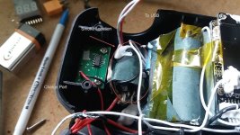
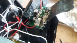
It seems there is a little board that goes to the USB port that popped a capacitor.
View attachment 2
20171018_154832.jpg

So i guess the capacitor on that board was really cheap? and that is why it blew?

After playing around with my multimeter I have:
-No power to the USB
-54v coming out of the main connector
-Nothing from the charge port

The positive charge wire to the charge port is all good as it comes directly from the battery but the negative wire comes from the BMS and there is nothing when I test this wire.

I was wondering if maybe that is a function of the BMS and it may charge anyway but I am not sure and don't want to just plug it in and see. I am guessing I should get 54v from the charge port as well???

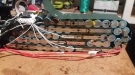
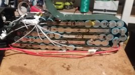
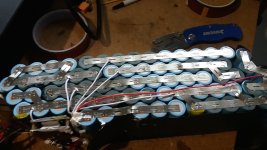
Take a look at the lack of series connections - this is suppose to handle 30amps continuous!! Looks like I still have some work to do.
20171018_174227.jpg
 
All joking aside...when a capacitor immediately pops upon its board being plugged-into a power-supply/battery?...the two major culprits are likely to be...

1) The manufacturer accidentally used a capacitor that was not rated for the required voltage, or...

2) The assembler accidentally soldered the capacitor into the two holes backwards. (positive lead to negative socket, negative to positive, etc...)

You might assume that any device as complex as this would be given a basic Quality Assurance (QA) test before shipping, but...you were being honest by including that you bought it off of Aliexpress, so...

I recommend you pull out the burnt capacitor and solder-in a better replacement ($2?), then...try it out to see if it also pops. The longer lead (out of two leads) on a raw/new capacitor is typically the positive.

PS, the BMS on any ebike battery is a complex electronic device, with there being many variations from one BMS to another, so...I am quite likely to be full of crap on this.

If you decide to use this sad event as an opportunity, consider charging to only 4.05V per cell (80%?), and eliminating the BMS completely. Sure...over time, the individual cells will slowly drift out of balance, but....as long as the total pack voltage is lower than the max, the highest oddball cell will not exceed 4.25V per cell, right?
 
spinningmagnets said:
All joking aside...when a capacitor immediately pops upon its board being plugged-into a power-supply/battery?...the two major culprits are likely to be...

1) The manufacturer accidentally used a capacitor that was not rated for the required voltage, or...

2) The assembler accidentally soldered the capacitor into the two holes backwards. (positive lead to negative socket, negative to positive, etc...)

You might assume that any device as complex as this would be given a basic Quality Assurance (QA) test before shipping, but...you were being honest by including that you bought it off of Aliexpress, so...

I recommend you pull out the burnt capacitor and solder-in a better replacement ($2?), then...try it out to see if it also pops. The longer lead (out of two leads) on a raw/new capacitor is typically the positive.

PS, the BMS on any ebike battery is a complex electronic device, with there being many variations from one BMS to another, so...I am quite likely to be full of crap on this.

If you decide to use this sad event as an opportunity, consider charging to only 4.05V per cell (80%?), and eliminating the BMS completely. Sure...over time, the individual cells will slowly drift out of balance, but....as long as the total pack voltage is lower than the max, the highest oddball cell will not exceed 4.25V per cell, right?

Lol - yeah I know buying batteries from Aliexpress probably not the smartest idea but I thought I might learn something by pulling it apart.....I might regret that thought :wink:

The BMS board seems to be ok, this was just a little board for the USB port that had the capacitor pop.

Strangely enough when I first got it i turned it on and checked voltage - all ok. The I turned it off took the battery into my shed then and the next time I turned it on it happened - kinda weird. Maybe it was option 2 - capacitor not rated for required voltage so it passed inital test but was eventually going to happen.

Anyway I don't really need the USB port anyway so I may just get rid of it.

My main concern is I have no voltage at the charge port. I do have 54v at the battery discharge connector so all good there.

It seems the negative from the BMS to the charge port is the issue.

Is that normal for some BMSs? Or should I have 54v there also? I don't want to just plug it in and see :?

Edit- Getting way out of my depth here but I don't know why they needed a capacitor for the usb port - I thought a resister would be needed to take the voltage down to 5v
 
Both the charge and discharge ports on a BMS will limit the external input and output (who knows what charger you will use? or what motor?)

Sounds like you will be unable to charge it? There is the possibilty that you could risk damaging everything by bypassing the BMS, and charging the battery directly at the positive and negative terminals of the cell-block portion of the pack?
 
Just think about the quality components, top engineering and great care that went into that BMS! :shock:
 
barbs00 said:
Edit- Getting way out of my depth here but I don't know why they needed a capacitor for the usb port - I thought a resister would be needed to take the voltage down to 5v

The little circuit borads in the 12v to USB "cigarette lighter/accessory" car sockets typically have a coil, a little IC, some capacitors and some resistors that are used to drop the 12v down to 5v. I'd assume that capacitor that popped on the little board was part of a similar circuit.

Not my area at all either. But these cheap converters would surely use a simple resistor if that would suffice. Right? And they don't.
 
They don't use a resistor because all the excess energy would be dumped as heat and it's inefficient and would be bigger and more expensive than a buck converter which is what they use instead.
 
Thanks Guys - I kinda expected this to be crap but this is an experiment for me.

I may even cut the battery into 2 7S5P units attached some more balance leads and balance with a hobby charger or maybe just replace the BMS entirely if it is no good.(still have to test it). I definitely need to weld on some more nickel strips. Some series connection are only a single piece of Nickel!


spinningmagnets said:
Both the charge and discharge ports on a BMS will limit the external input and output (who knows what charger you will use? or what motor?)

Sounds like you will be unable to charge it? There is the possibilty that you could riak damaging everything by bypassing the BMS, and charging the battery directly at the positive and negative terminals of the cell-block portion of the pack?

To be used for a BBSHD, I have a Meanwell HLG that I use for my normal charger this also came with an Aluminium standard 58.8 charger. I haven't tried to charge it yet...will let you know how I go

Out of curiosity does anyone know where I can get a new board for the USB? May be easier than soldering a new capacitor.
 
FYI, I checked my 48V dolphin which has an on/off switch.

1) The charger port shows no voltage if I put a meter on it, unless I turn the battery on. Then it shows 48V.

2) However, I can plug in a charger with the battery turned off, no voltage showing on the charge port, and it starts charging.

So maybe your battery will charge.

The USB board is probably something they bought for 75 cents, and it's going to be a complete unit with filter caps, etc. Probably inserted backwards, or just defective. It happens.
 
docw009 said:
FYI, I checked my 48V dolphin which has an on/off switch.

1) The charger port shows no voltage if I put a meter on it, unless I turn the battery on. Then it shows 48V.

2) However, I can plug in a charger with the battery turned off, no voltage showing on the charge port, and it starts charging.

So maybe your battery will charge.

The USB board is probably something they bought for 75 cents, and it's going to be a complete unit with filter caps, etc. Probably inserted backwards, or just defective. It happens.

Thanks docw009 that is very helpful. I will try charging it tonight when I get home from work.
 
There's nothing on the charge port because it's already fully charged. The charge mosfet has therefore most likely switched off. I'd just remove the USB module and use the battery normally.
 
Well - the battery seems to charge fine so that is good but after further investigation I have found.

1. The balance wires seems to be attached all over the place except where they are suppose to - see photo
-some parrallel cell groups have no balance leads attached at all and some have them attached to the positive and negative terminals
20171019_223651.jpg

20171019_223653.jpg
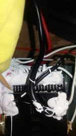
2. They have used a 16S BMS instead a a 14S for 52v.
-The final 2 wires are not attached to the cells.
20171019_221906.jpg

3. The negative balance wire is soldered to the negative input terminal of the BMS

The guy who did this is either incompetent or really doesn't give a f*#K.

So....
- Is the 16S BMS ok or not?? I thought they had to be matched exactly but then again this battery is working, I am just not sure if the BMS will balance (if I fix the wires), and protect from low/high voltage??

-Is it ok to have the negative balance wire soldered to the negative input terminal of the battery. This essentially means it is attached the the negative of the 14th group of cells. I thought is was suppose to go on the 1st group?

Geez - getting there!

Appreciate the help all!
 
Maybe it's not too bad. Some 16s BMS can be set up to work as 14s. It's possible, at least. Also, it doesn't really matter whether the balance wire is hooked up to the negative side of a group or the positive side of the next group that it's connected to. So it's sort-of OK to have two balance wire connected to the two sides of a single group.

I'm not saying it's a well built pack, though.
 
I guess your best outcome with Alixpress would be to allow you to send it back as long as you pay for shipping.
If the core of the pack still works I would just leave it as is unless you need the USB port. Its possible the cap going is a sign of a bigger problem of the USB module and the cap ended up going where a fuse would have been prefered.
 
TheBeastie said:
I guess your best outcome with Alixpress would be to allow you to send it back as long as you pay for shipping.
If the core of the pack still works I would just leave it as is unless you need the USB port. Its possible the cap going is a sign of a bigger problem of the USB module and the cap ended up going where a fuse would have been prefered.

You can buy 48v to 5v dc converters on ebay starting at a couple of dollars. So removing the failed board and replacing it would probably be pretty easy and cheap.
 
tanstaafl said:
Maybe it's not too bad. Some 16s BMS can be set up to work as 14s. It's possible, at least. Also, it doesn't really matter whether the balance wire is hooked up to the negative side of a group or the positive side of the next group that it's connected to. So it's sort-of OK to have two balance wire connected to the two sides of a single group.

I'm not saying it's a well built pack, though.

You are right - After another look I can see a pattern. They have either wired the balance wires to the positive end, or the negative end of the same group instead of the positive of the next group. (Does that make sense?)

It also seems they have attached all the wires backwards - so from the BMS the B- 14th group, B1+ 14th group, B2+13th group etc

I will pull out the connector on the BMS and makes sure it goes up in 3.6v increments.

Is there any way to check if the balance charging is working?

chvidgov.bc.ca said:
Did you check the relay on the on-off switch. I had one of those burn out on a pack like this...they are lower spec than they should be. I ended up wiring around it to get the pack to work.

No but I will now while I have it apart. Good thinking

TheBeastie said:
I guess your best outcome with Alixpress would be to allow you to send it back as long as you pay for shipping.
If the core of the pack still works I would just leave it as is unless you need the USB port. Its possible the cap going is a sign of a bigger problem of the USB module and the cap ended up going where a fuse would have been prefered.

I think I will just try and negotiate some money back - I didn't really expect this to be wonderful.
As long as the cells are genuine I don't mid fixing it - I will have to discharge the pack and check capacity. Probably by taking it for a ride (after I add some more series connections)


wturber said:
You can buy 48v to 5v dc converters on ebay starting at a couple of dollars. So removing the failed board and replacing it would probably be pretty easy and cheap.
Yeah_ i think I will do that

Thanks all!

Edit - I take it all back. After playing with my Multimeter it seems the balance wires do go up in 3.6v increments. A strange way to wire it but at least it works
 
It's actually not too weird, it just seems that way at first. Since the positive of one group is hooked right to the negative of the next, even if it's soldered near the "positive" end of the strip connecting them, the bms still see it as negative.
It's sort like hooking up 12v blocks... It just feels weird plugging red to black at first... But then you realize it doesn't matter, until you get to the end of the series anyway.
 
In case anyone is still interested.
I added the required series connection then managed to mount the haillong battery to the bottle brackets ( after drilling some holes in the bottom of the battery attachment) and went for a ride today.

My other pack is 52v 14AhLG MG1 cells and this is 52v 16Ah LG MH1 cells - Power and top speed seems very similar, voltage only dropped about 5v after a decent ride. These cells seem to be good so far. I will go for a long ride and see how far I get to check capacity.

Oh.. I simply pulled out the DC-DC converter board to the USB. I might replace it one day

Thanks for your advice all
 
Back
Top