DIY BLDC Controller Wave forms + Snubber

glenn0010

100 W
Joined
Jul 1, 2015
Messages
117
Location
Mgarr, Malta
Hi all,

I am doing my final year thesis in electronics and control. I have built a prototype board for my BLDC motor controller. The board has a lot of test points and jumpers so I can manipulate components in and out of circuit to see what effect they have on the wave forms.

What I want to test for now is:

1. The effect of the electrolytic capacitor in parallel with the ceramic bootstrap capacitor.
2. The effect of the diode in parallel with the gate resistor
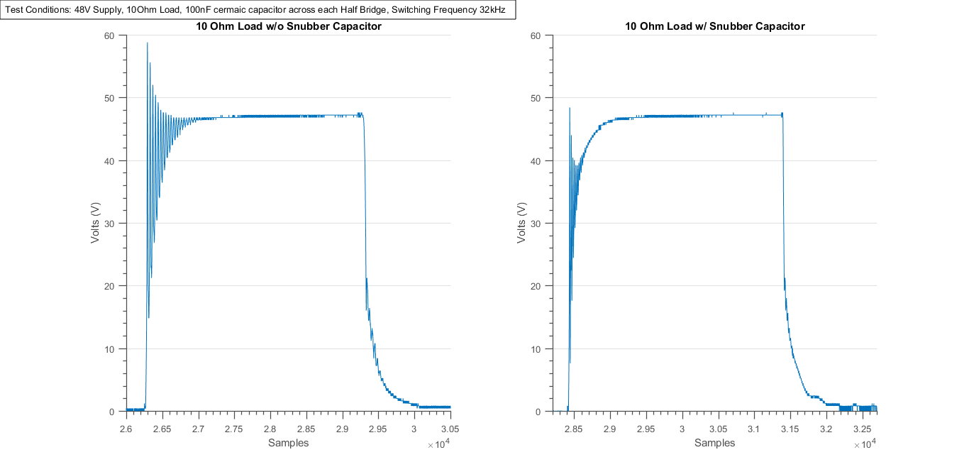
3. Effective Snubbing to have clean 'power' wave froms

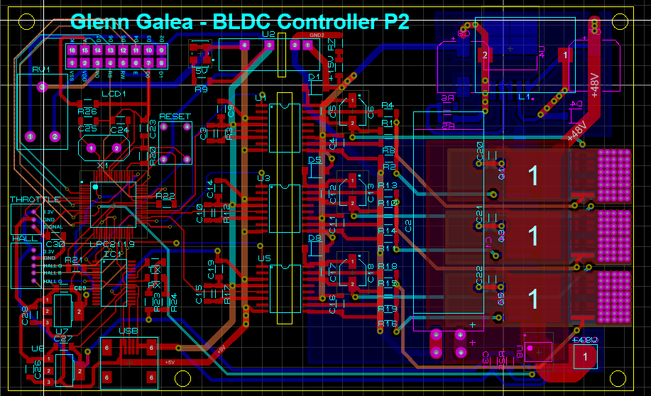
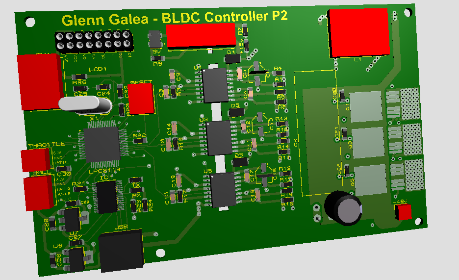
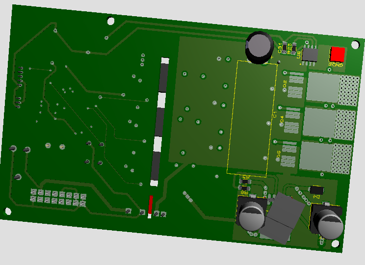
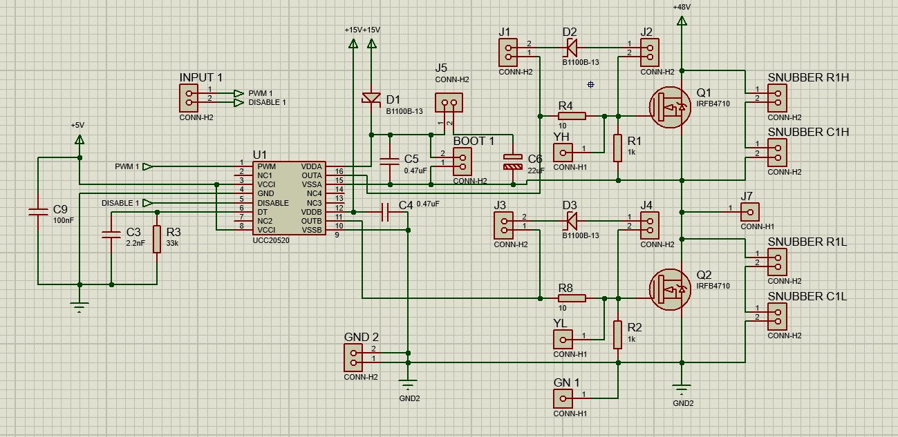
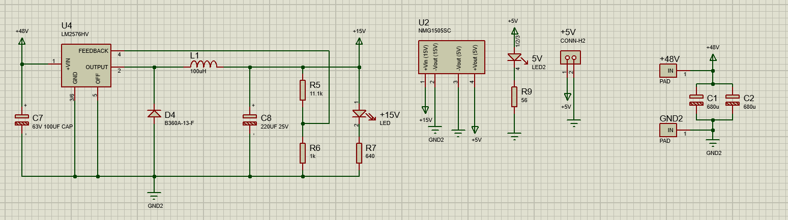
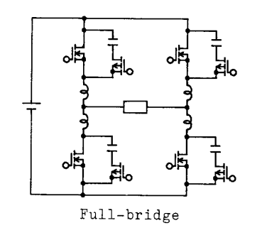
Below are the schematics:

xpgPBPv.png


qc2899U.png


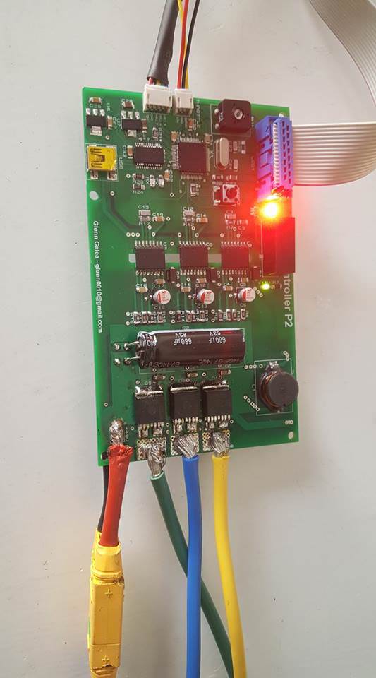
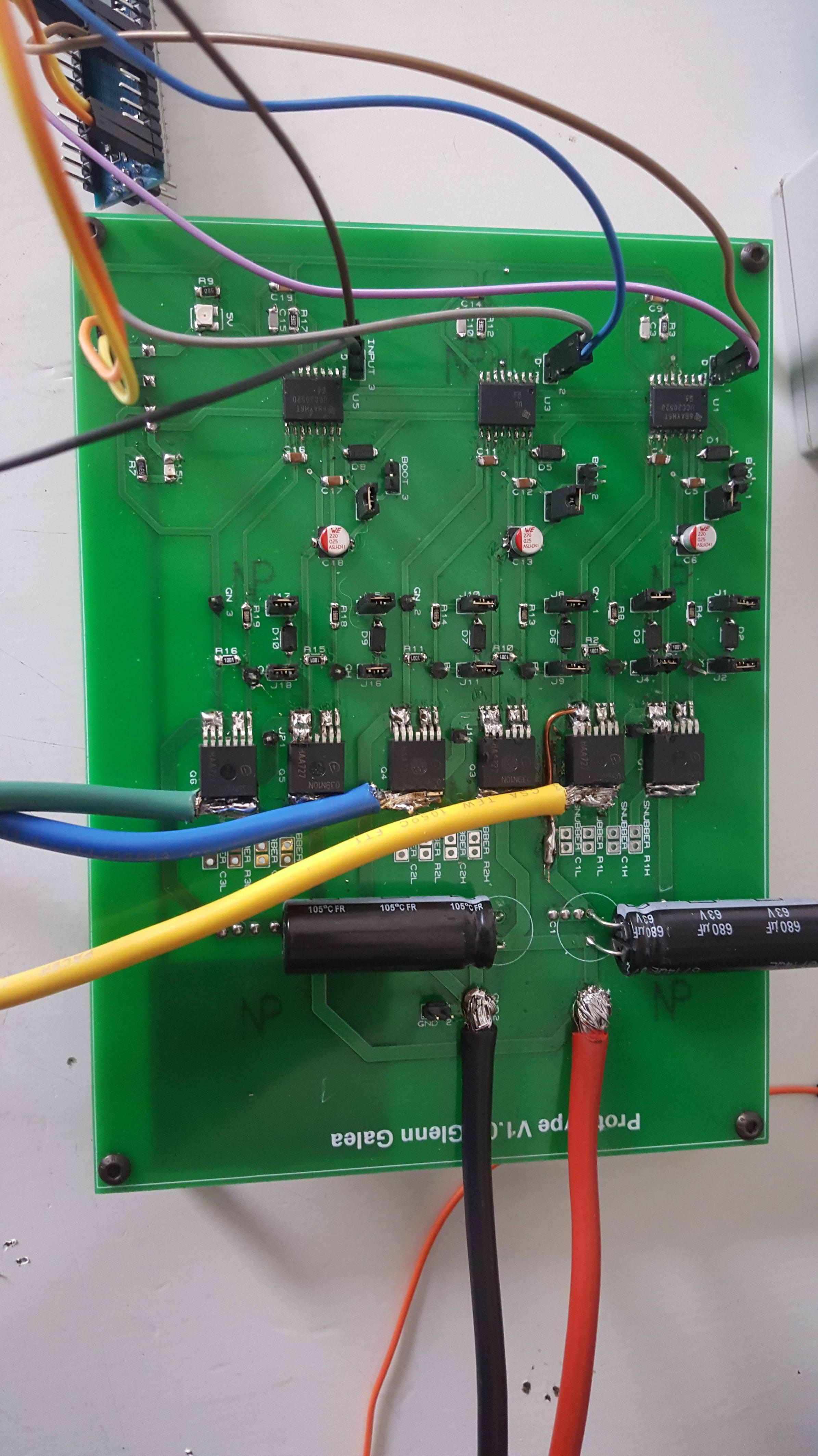
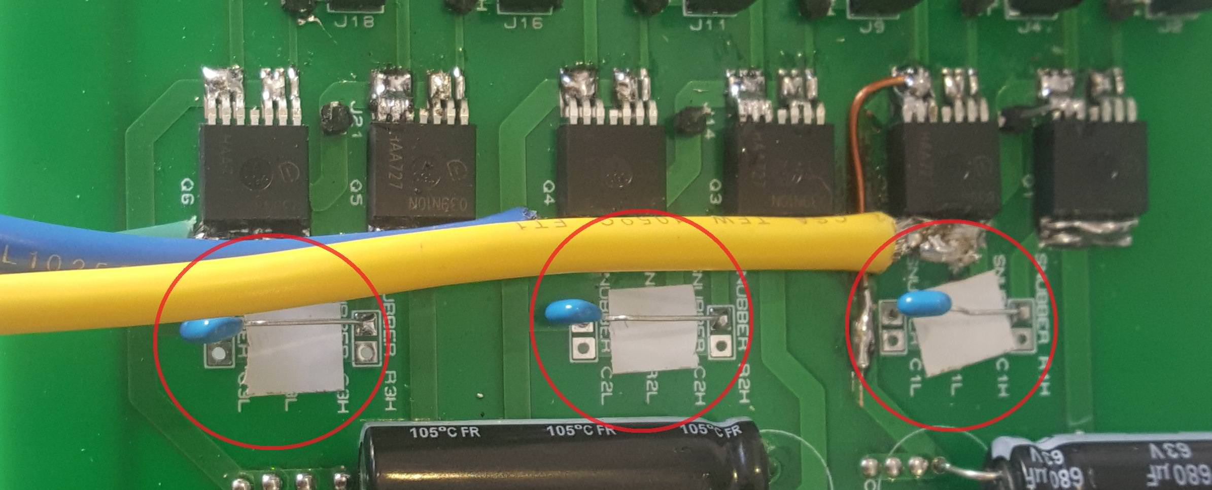
And here is my soldered board:

uwXU4Kd.jpg


I tested the functionality of all the FETs using a 10 Ohm load resistor. I put the probes across the load resistor and here are the waveforms I got:

cWZL3nV.png

lDoNelP.png


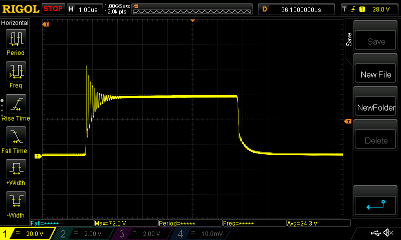
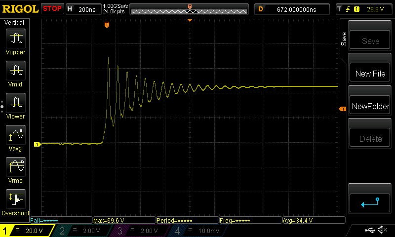
I measured the ringing frequency at around 13.2 MHz. I obviously want to eliminate this ringing and that nasty voltage spike. My FETs V[sub]DS[/sub] is rated at 100V however I want to eliminate this.

I have read several papers and application notes on Snubbing and from what I understood and from the equations it seems that the voltage spike and ringing is to do with the stray inductances of the components traces etc (L[sub]LK[/sub]).


I have used this AN from NXP as my main guide. https://assets.nexperia.com/documents/application-note/AN11160.pdf


I do have some questions though:

1.Do I just need an RC snubber circuit across the high side FETS as the NXP AN seems to State?
As this document from TI seems to inidcate that the RC snubber should be placed across the low side FETs : http://www.ti.com/product/CSD88599Q5DC/datasheet/layout?

An I have found this source that indicates snubbers across both sides
uWShPc5.png


2.Could I get away with placing just 3 ceramic caps across each half bridge as I just have big fat electrolytics across the POWER rail which are useless for this kind of thing.?


Sorry for the questions but I am a bit confused.
 
glenn0010 said:
2.Could I get away with placing just 3 ceramic caps across each half bridge as I just have big fat electrolytics across the POWER rail which are useless for this kind of thing.?[/color]

I'm not a real expert on this stuff, but I have reverse engineered a lot of controllers. I would try placing some MLCCs on the power rail and see what happens. This is very easy to try and can't really hurt. I see this in most designs.
 
fechter said:
glenn0010 said:
2.Could I get away with placing just 3 ceramic caps across each half bridge as I just have big fat electrolytics across the POWER rail which are useless for this kind of thing.?[/color]

I'm not a real expert on this stuff, but I have reverse engineered a lot of controllers. I would try placing some MLCCs on the power rail and see what happens. This is very easy to try and can't really hurt. I see this in most designs.

Thanks I will give it a shot!
 
fechter said:
glenn0010 said:
2.Could I get away with placing just 3 ceramic caps across each half bridge as I just have big fat electrolytics across the POWER rail which are useless for this kind of thing.?[/color]

I'm not a real expert on this stuff, but I have reverse engineered a lot of controllers. I would try placing some MLCCs on the power rail and see what happens. This is very easy to try and can't really hurt. I see this in most designs.

Hey Fetcher thanks for the response. I added 100nF ceramic caps across each half bridge and it worked a treat! Thanks so much!

YtiJsis.jpg


3wLmvmW.png


The previous voltage spike was almost 60V and now the voltage spike is barely over 48V! So that is a huge improvment!!

Open the images in another tab to see the full picture as they are not resized for some reason
 
Looks great.

One thing I've noticed before when trying those kind of measurements is you often get 'artifact' from the probe leads, especially if the ground wire is too long. The other thing will be to make the same measurement with an actual motor load. Motor inductance is a big factor.
 
fechter said:
Looks great.

One thing I've noticed before when trying those kind of measurements is you often get 'artifact' from the probe leads, especially if the ground wire is too long. The other thing will be to make the same measurement with an actual motor load. Motor inductance is a big factor.

Yes definitely the best way to do this is to solder actual probes on where you are probing and having short leads as you said. No I will do exactly what you said, I will connect two phases of the motor as the loads and will start at lower DC link voltages for safety.
 
You should also be aware that faster switching (short rise and fall times) will produce larger overshoot.
In typical ebike controller switching losses are small portion of conduction losses since switching frequency is low.

You use very fast gate driver and low 10ohm gate resistor. check this schematic of generic ebike controller where they use 100ohm gate driver resistor and 10nf capacitor in parallel with gate capacitance! by doing this they deliberately slow down transition times so there is virtually no overshoot. that makes controller bit less efficient but bulletproof. There are people on this forum that are using 100V batteries in combination with controller with 100v mosfets. Crazy but it works, at least for some time. :)

Best regards,
Dusan Latinovic


http://www.avdweb.nl/Article_files/Solarbike/Motor-controller/China-BLDC-motor-controller-36V-250W-circuit.jpg
 
Dulel said:
You should also be aware that faster switching (short rise and fall times) will produce larger overshoot.
In typical ebike controller switching losses are small portion of conduction losses since switching frequency is low.

You use very fast gate driver and low 10ohm gate resistor. check this schematic of generic ebike controller where they use 100ohm gate driver resistor and 10nf capacitor in parallel with gate capacitance! by doing this they deliberately slow down transition times so there is virtually no overshoot. that makes controller bit less efficient but bulletproof. There are people on this forum that are using 100V batteries in combination with controller with 100v mosfets. Crazy but it works, at least for some time. :)

Best regards,
Dusan Latinovic


http://www.avdweb.nl/Article_files/Solarbike/Motor-controller/China-BLDC-motor-controller-36V-250W-circuit.jpg

Wow thanks for that link!

In my eyes that is such a complex way of doing things, discrete components everywhere rather than using and integrated gate driver for example like I did. I am sure the way they did it is a lot cheaper since the gate driver alone costs 5 euros each and I have isolated DC to DC converters.

I have now designed a fully integrated version of my controller. Waiting on the components to come in from mouser so I can check the footprints and then I can order the PCBs.

Here is a sneak peak of the 3D rendering

wdALwqS.png


ytCgXmP.png


WX0O3kk.png
 
johnrobholmes said:
Looks like a cool project. Hook some motor up and see how stable to gates are.

I already hooked a motor to it and it works well! Now I just need to construct the new smaller board and see how it works.
 
So here is Prototype 2 (P2). She is working :)

It is a 4 layer board whose FET layout is inspired by Vedder. Got total isolation from the logic side to the power side. This includes isolated current sensing as I am using Hall effect current sensing. Was my first time soldering QFN packages so I did butcher the Micro but it works.

It works well. Now looking t moving forward and running some thermal tests on it. Also looking at comparing trace inductance with the first version seen in the posts above.

In the mean time I have been working on P3 which will be similar to P2. However P3 will have temperature sensing, and an integrated 3 Phase Full Bridge (MTI85W100GC). Also the P3 will feature REALLY short tracks between the Gate Drivers and fets, since they will go from the top of the board to the bottom. This is aimed at reducing the inductance and hence making the circuit more hardy.
Any suggested Improvements of the P2 for the P3 are welcome

dzsmlyx.jpg
 
Yes definitely in the P3 there will be a dedicate heat sink. however I think the P@ can still take a fair amount of current with the power plans as makeshift heat sinks.
 
Back
Top