Let me preface this with a couple of statements so everybody knows where I'm coming from:
1. The CAv3 is great. I love it and I haven't seen anything I like better.
2. I've had a really shitty day -- and it's my birthday. I took the day off from work and decided to "have fun" working on my bike. It wasn't fun.
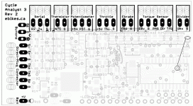
But, those two things aside, I really feel that I'm right about the title. It SHOULDN'T be this hard. My current object of ire is this CAv3 I just said I love. It's a love-hate relationship, clearly. Why do I have to pull out a soldering iron to modify something on a small unit that's really NOT designed well for amateur soldering modifications? Really, I'm used to this stuff with hobby equipment, but the board on the CA just isn't all that easy to work with -- the parts are all tiny these days and space is kinda cramped when you're doing something to the board. It just shouldn't be necessary. And I seem to be having a perfect storm of needs to modify my CA. I'm not talking about something esoteric, I'm talking basic stuff:
1. EM3EV sells Mac motors and sells CAs to use with them, so I thought, I could just order the motor and use it with my existing CA -- what could go wrong? Well, they put in a temperature sensor that's not compatible with the CA unless you pull out your soldering iron and remove a resistor and add another one (and maybe add a cap also, though I didn't do that part). Why not just stick to what would work? A 10K thermistor isn't as good as the sensor that was built into my motor, BUT I DON'T CARE. It would have worked out of the box with no soldering on my existing CA.
2. And, of course, I had the wrong version of the CA to begin with, because I was using the same one I had on my older direct drive motor. I had to add a speed sensor and solder it onto the CA board. Why not just have an extra connector on the back? (and then have a CA configuration for which one input to use for speed) Would it really raise the price that much?
3. Then I bought a TDCM -- something also sold to work with the CA, so no problem, right? NO. With the TDCM and my battery voltage, I've got to do surgery on the freaking thing ONE MORE TIME! Because the battery voltage is so high, the CA can't supply enough power (to TDCM, throttle, ebrakes, etc.), so I have to wire in an external regulated power supply and wire up the battery voltage to another pad (yet more soldering) and, oh by the way, add a couple more resistors, move a solder bridge, etc. Would it really have cost that much to just put in a freaking circuit board mounted switch? They're pennies, really.
And then there are all the other things I wish were better on the CA. The display, honestly, sucks. It was OK-ish a few years ago, but times have changed. You can buy an android phone for less than $50 with an awesome display built in. Now I know CAs will never be made in the billions like phones are, but here's the thing -- you don't have to build a fancy display. Hundreds of phone manufacturers are willing to do it for you! Just build in the controls and smarts into the CA and let people use their own phones for the display. Even if somebody doesn't want to use their own $1000 iPhone or Galaxy, it's not a big hurdle for them to pluck down the money for a sub-$50 phone just to use it as a dedicated display! Then you could add some really nice stuff to the interface app (and even charge extra for those nice things to get some extra profit!). Stuff like automatic logging, GPS and map display, all the data currently displayed on the CA but in a bigger, clearer, display, ... Integrate it with the communications with a nice bms so that you can monitor individual cell voltages from the same display.
And why are there so many WIRES? And all of them different! Why not standardize on a bus and just use the same couple of wires for hooking up all the peripherals? This isn't a new concept, unless you're working on an ebike.
And why doesn't the controller already supply the kind of voltage the CA would need? Especially controllers that are built with the CAv3 wiring already attached! If you know you're building a controller that can handle a lot of volts, guess that people are buying the controller to USE a high voltage battery and know that the CA has power supply problems with high voltage sources. Sell the controller with the solution already built in. Instead, people are told to cobble together a hacked up POS that uses a laptop power supply or something like that.
And why...
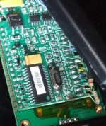
Rant over. My latest little fiasco was that when I went to move the solder bridge, I apparently lifted the pad off the board and took it away with the solder. Naturally, it was the middle pad that lifted -- either of the other two would be easy to work around (the lower one isn't even needed any more and the upper one is a from a board input just a fraction of an inch away). If anybody can tell me where to connect my voltage in, so that I can make this thing work, I'd appreciate it. Maybe I'll get somebody actually competent at soldering these tiny little connections to do this for me.


