Fitting PAS to square BB on road bike

Lovelock

10 W
Joined
Mar 24, 2018
Messages
72
Hi, trying to figure out how to fit PAS to my road bike project.

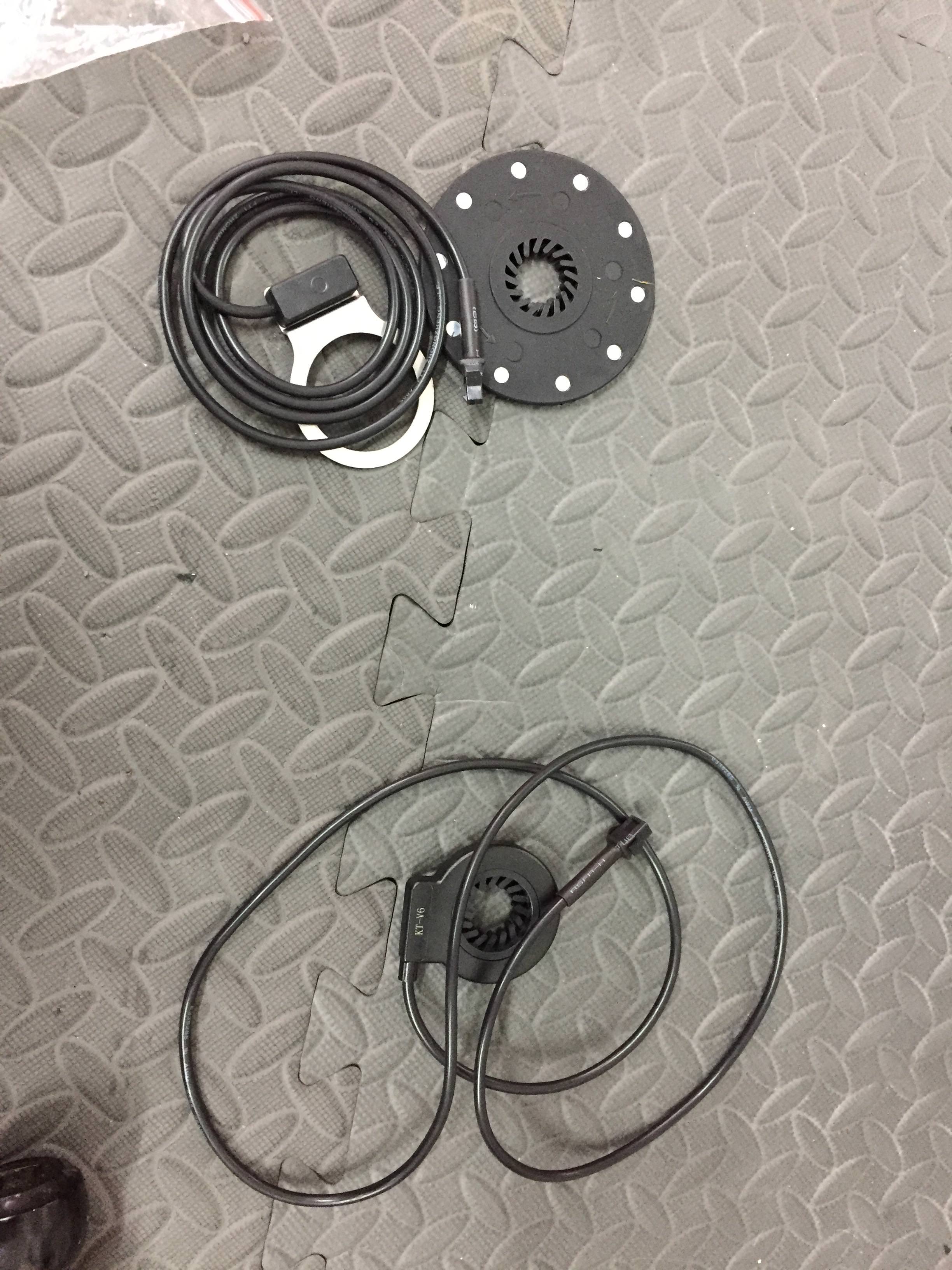
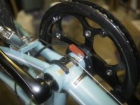
Here are both the sensors I have:

0L1nkEm.jpg


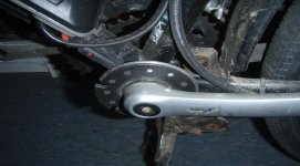
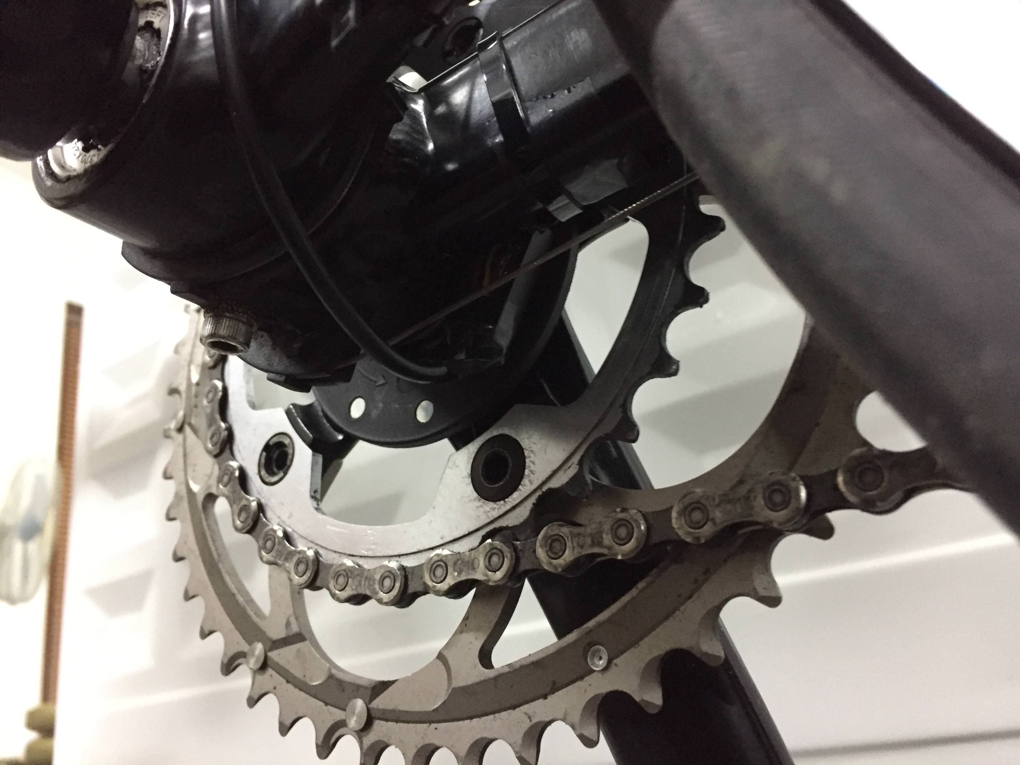
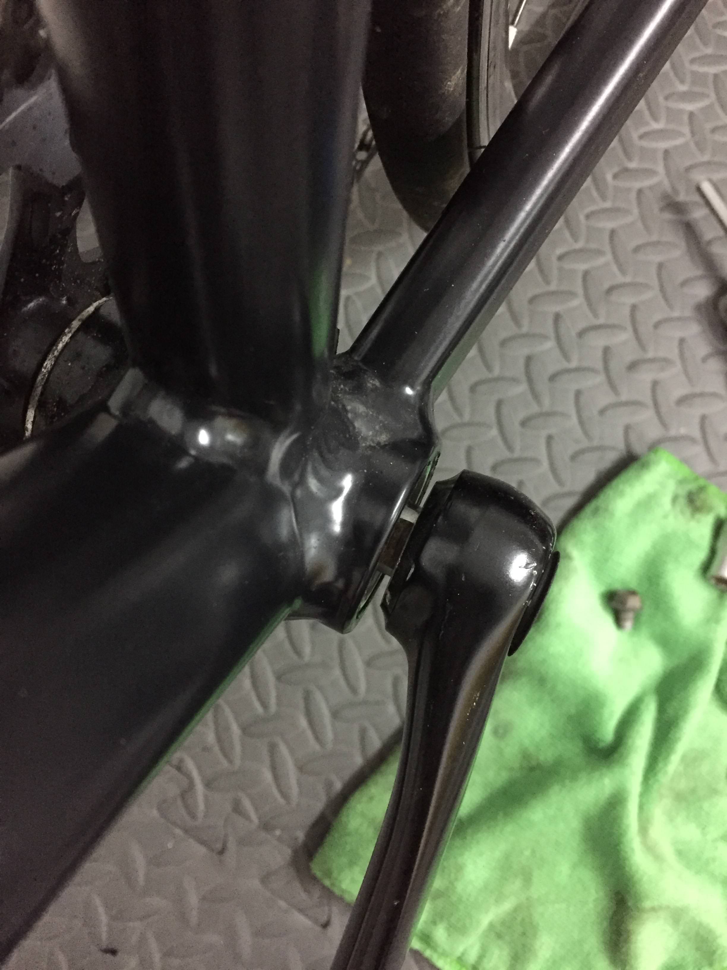
I've taken off my crank arm and test fitted the lower sensor from the picture:

xYDbVPL.jpg


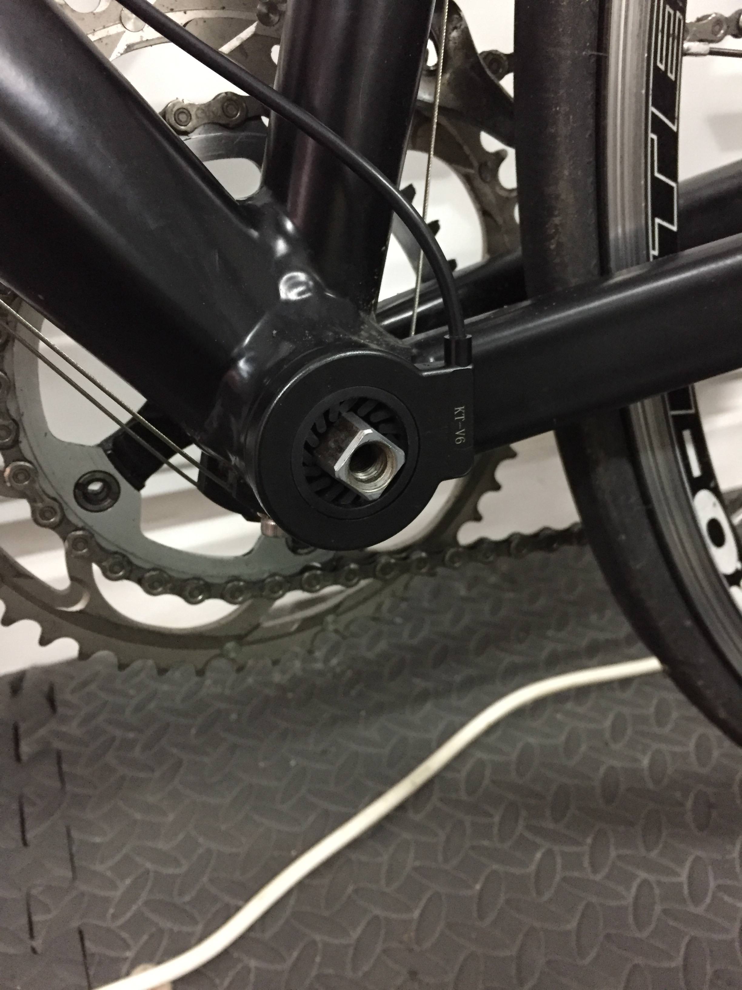
I've then refitted the crank arm:

vCei0c0.jpg


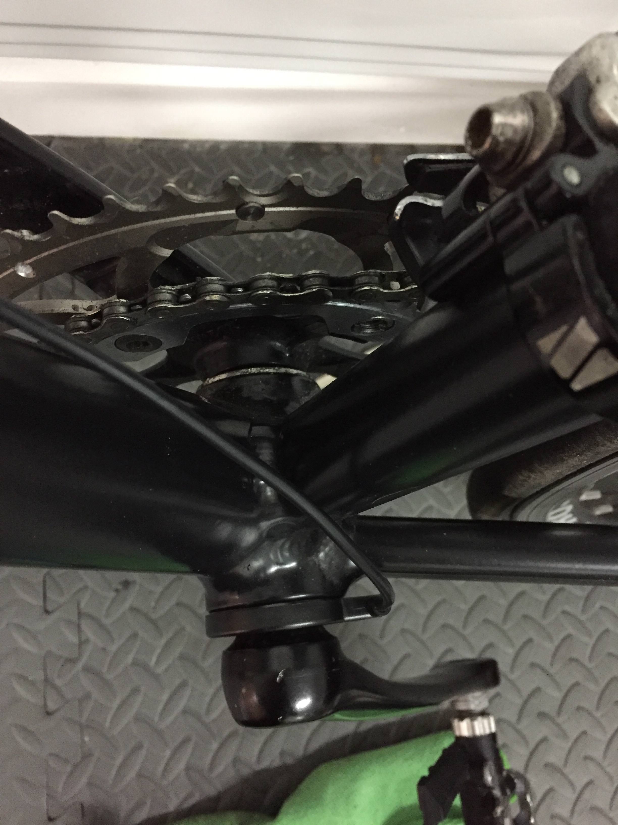
Something about this feels incorrect? Its pushed the crank arm out and there is less thread now being used on the bolt but it does stay in tight. Should the sensor be cable tied so it doesn't rotate?

Anything I've done wrong here?
 
Lovelock said:
Hi, trying to figure out how to fit PAS to my road bike project.
...
Anything I've done wrong here?
Yep - looks like it.

The critical missing picture is one of the crank and BB before the installation. It looks like you sensor is too thick for the available BB shaft. I suspect that you have compressed the inner sensor wheel up against the inner bearing race (or similar) and that the crank is tightening against the inner plastic element instead of seating on the shaft taper. This is why it's displaced outward and fewer threads are engaged. It probably won't survive much pedaling before fracturing.

The other sensor may fit - you need to eyeball the gap before installation.

If that won't work you can mount the magnet wheel on the right side on the inner chain ring. There are sensors made to do this (similar to the CA3 version: PAS_12P_Chr for Grin Tech) but you can fake it yourself with what you have.

  1. If there is insufficient BB shaft on the chain ring side to mount it normally (probably won't be), then you can cut out the center section of your other sensor wheel (use a coping saw or large UniBit), drill a few holes in it and zip tie it to the arms of the chain ring - or something similar - you are in wing-it mode for the fastening business. Before you mount up the magnet wheel on the other side, wave the sensor past it in the direction of crank rotation and check that it works. The sensors are typically direction sensitive and you will likely need to flip over the wheel when the sensor is on the opposite side (i.e. the embossed 'direction arrow' will be pointing in reverse).
  2. Another option is to epoxy some neo magnets to the chain ring arms. This will probably only give you 5 magnets which won't be too responsive compared to the 10 magnet wheel you have, but it will work okay. If you use grade 52 magnets, they should stick to the chain ring bolt heads w/o the epoxy and are strong enough to not require the sensor to be super close.

In either of these cases you will probably need to fudge the sensor mount. You can bend this as needed and in a pinch use a hose clamp to affix it to the BB, seat tube, or down tube.


80-14_pickupInSitu.jpg
 
re: "If there is insufficient BB shaft on the chain ring side to mount it normally (probably won't be), then you can cut out the center section of your other sensor wheel (use a coping saw or large UniBit), drill a few holes in it and zip tie it to the arms of the chain ring - or something similar - you are in wing-it mode for the fastening business. Before you mount up the magnet wheel on the other side, wave the sensor past it in the direction of crank rotation and check that it works. The sensors are typically direction sensitive and you will likely need to flip over the wheel when the sensor is on the opposite side (i.e. the embossed 'direction arrow' will be pointing in reverse)."

This is more or less what I did, but I epoxied the sensor wheel to the crank vs zipties. Has been working fine for over a year, i.e. several thousand miles. Well, mine is on the non-drive side.
 
Thanks for the responses guys, D8veh over on Pedelecs suggested grinding off the tapered section from the inside of the crank arm. This should give me around 5mm more clearance which should give me the room I need.

For reference, heres the arm without sensor:

f8atDyx.jpg
 
In the same spirit of DIY, here's my most recent sensor install. I used a convenient cable guide to hold the bracket.

I've never had a BB where the round ring of the PAS bracket would have fit under the BB end pieces.
 

Attachments

  • PAS-2.JPG
    PAS-2.JPG
    78.1 KB · Views: 1,190
Lovelock said:
...D8veh over on Pedelecs suggested grinding off the tapered section from the inside of the crank arm.
I wouldn't pursue that approach myself - that would be modding/weakening a major pedaling component to mount a little bit of plastic.

If you really don't want to go for the drive side mod, then go with the change OW54 implemented which was actually a pretty neat solution. You should be able to drill out the simpler PAS wheel and mount it up on the taper section of the crank. Or - if you have a thin scrap of plastic (ABS or some non-polyethelene stuff so it can be epoxied) you might cut a small circle slightly larger than the tapered crank boss and drill a hole in it for an interference fit onto the BB taper. This would give you something to essentially replace the multifinger thingie you will be drilling out of the PAS wheel - the wheel itself would be glued to it and offset outward over the crank taper. Anyhow - several options there that would avoid modding the crank proper...

oldwahoo54 said:
... I epoxied the sensor wheel to the crank....
... mine is on the non-drive side.
 
docw009 said:
In the same spirit of DIY, here's my most recent sensor install. I used a convenient cable guide to hold the bracket.

I've never had a BB where the round ring of the PAS bracket would have fit under the BB end pieces.

I like the idea of placing the sensor underneath, i'll make a new bracket tomorrow and see what I can do.
 
teklektik said:
Lovelock said:
...D8veh over on Pedelecs suggested grinding off the tapered section from the inside of the crank arm.
I wouldn't pursue that approach myself - that would be modding/weakening a major pedaling component to mount a little bit of plastic.

If you really don't want to go for the drive side mod, then go with the change OW54 implemented which was actually a pretty neat solution. You should be able to drill out the simpler PAS wheel and mount it up on the taper section of the crank. Or - if you have a thin scrap of plastic (ABS or some non-polyethelene stuff so it can be epoxied) you might cut a small circle slightly larger than the tapered crank boss and drill a hole in it for an interference fit onto the BB taper. This would give you something to essentially replace the multifinger thingie you will be drilling out of the PAS wheel - the wheel itself would be glued to it and offset outward over the crank taper. Anyhow - several options there that would avoid modding the crank proper...

oldwahoo54 said:
... I epoxied the sensor wheel to the crank....
... mine is on the non-drive side.

I'm not dismissing any ideas right now, didn't fully understand yours / OW54 suggestions at first but now I get it.

Will check tomorrow how much room there is around that side.
 
Lovelock said:
docw009 said:
In the same spirit of DIY, here's my most recent sensor install. I used a convenient cable guide to hold the bracket.

I've never had a BB where the round ring of the PAS bracket would have fit under the BB end pieces.

I like the idea of placing the sensor underneath, i'll make a new bracket tomorrow and see what I can do.

My cheap red unit better be waterproof. Think I'll run a bead of silicon around the edges,
 
Lovelock said:
I'm not dismissing any ideas right now, didn't fully understand yours / OW54 suggestions at first but now I get it.
I think you have it - but just in case:
A picture is worth... :)


Stepped bits are available for cheap at Amazon, Harbor Freight, etc. Handy...
When drilling you just need to clamp the magnet wheel securely and maybe put a sacrificial backstop of wooden scrap under it for support.

E6000 or one of the 'Goop' products (e.g. Amazing Goop, etc) (all from Eclectic Products - see Amazon, hardware stores, Home Depot, etc) might be an alternative to epoxy - it cures tough and rubbery and won't crack or fracture if it takes a hit. Needs 3 days to cure though... :( If you puddled a bit over the back of the wheel from the fillet, it would hold the wheel in place as a shaped rubber lip glued to the crank even if it didn't bond well to the wheel itself (though it seems to stick to just about anything).


noPasSpaceCrank.png


I haven't tried either of these mounting schemes but they should work okay...
Anyhow - good luck with your PAS project.
 
teklektik said:
Lovelock said:
I'm not dismissing any ideas right now, didn't fully understand yours / OW54 suggestions at first but now I get it.
I think you have it - but just in case:
A picture is worth... :)


Stepped bits are available for cheap at Amazon, Harbor Freight, etc. Handy...
When drilling you just need to clamp the magnet wheel securely and maybe put a sacrificial backstop of wooden scrap under it for support.

E6000 or one of the 'Goop' products (e.g. Amazing Goop, etc) (all from Eclectic Products - see Amazon, hardware stores, Home Depot, etc) might be an alternative to epoxy - it cures tough and rubbery and won't crack or fracture if it takes a hit. Needs 3 days to cure though... :( If you puddled a bit over the back of the wheel from the fillet, it would hold the wheel in place as a shaped rubber lip glued to the crank even if it didn't bond well to the wheel itself (though it seems to stick to just about anything).


noPasSpaceCrank.png


I haven't tried either of these mounting schemes but they should work okay...
Anyhow - good luck with your PAS project.


Thanks for the diagram!

I wen't with the suggestions previously mentioned. Ive removed the center of the disc and will be mounting it on the chain ring. I've also found a spot on the frame where the sensor can be mounted easily.

Will post pictures once all in place.
 
Here's a picture. Should be able to see the bead of epoxy, and the pickup sensor behind (upper left).
 

Attachments

  • P4190001small.JPG
    P4190001small.JPG
    79.6 KB · Views: 1,080
teklektik said:
Excellent!
That was certainly more of a project than you planned, but there's always something satisfying about cooking up a custom solution...
Enjoy your PAS!
:D

Hey, that post above wasn't me (incase you thought it was)

I decided to epoxy the ring on the inside of the chain ring and for testing have mounted the sensor underneath. I'm trying to keep the build as subtle as possible so preferred it inside the chain ring.

I need to mount the sensor better but it works as it is for now as i'm still in the testing phase.

The whole project has been more DIY then I expected! It seems road bikes are not really designed for being converted as much as Hybrid / Mountain bikes. But riding it last night felt great!

ZJN3ijS.jpg


Need to get a better picture as its difficult to see, but that kind of the point!
 
Lovelock said:
Hey, that post above wasn't me (incase you thought it was)
Whoa! You called that one exactly right - I confess I was surprised because you had said you were going with the chain ring mount - should have been a tipoff.

Lovelock said:
But riding it last night felt great!

Well, in any case - OW54 did a neat job and ditto my post again for your own mount (now that I'm looking at the right pic)!
 
Back
Top