No F*ing idea Friction drive

Bluefang

10 kW
Joined
Aug 27, 2010
Messages
589
Location
Australia, Goldcoast
Ok, to put it bluntly i have no idea about electronics past basic soldering, no idea about electric motors and hall sensors and no idea about how to plan a build. But damn its great fun when something works the way it should :twisted:

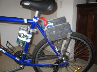
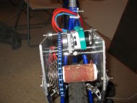
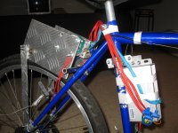
Reading this forum has really inspired me to see if i could build a electric bike, been a handyman i hoped i had enough sense to be able to take a whole lot of different ideas from other peoples posts and work them into something good. I have been reading the posts a fair bit, my plans have changed from a scooter build like Gwhy, to a bike build like Burtie and now finally to get my teeth into something i decide to try a Friction drive. I wanted it to be abit different in that most of the highend force increasing friction drives i have seen are mounted from the seat post, this is not going to work if i wanted to put it onto a full suspension bike which will be the end game with a 7kw+ motor etc......in a long time tho. I looked at the way the drives moved along and into the wheel as they increased in power and to get the same effect i have mounted my drive off the angled support tubes(no idea what to call them really) for the rear wheel with a smaller radius of travel so that it digs into the wheel about 2cm over a 10cm travel.

The parts.
The motor is a Turnigy SK 50-65 270 http://www.hobbyking.com/hobbyking/store/uh_viewItem.asp?idProduct=7709
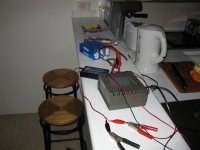
The controller is WAY overkill 12fet Lyen controller with throttle, 3 set switch
Halls added to a PVC ring around motor at 120 intervals
3x4S turnigy 5ah 20C, overkill again :roll:
12 Tooth bike sprocket ebay
Adapter to mount the sprocket onto the motor $65 :cry:
Bunch of free scraps of Alloy
$30 worth of threaded bar, bolts and nuts.
Roller is a hacked up rear hub from a scrap bike i found in some local street that i have Epoxied a PVC pipe over and then glued some old sand paper onto that.

All up cost me about $500AU, the bikes a 10yr old steel mountain bike
The bike works, can get up to about 18mph at 50% setting on the controller, i have not tried 100% as the motor is getting hot as it is and i dont think my halls are really in the right position
Picture 001.jpg
Picture 002.jpg
Picture 003.jpg
View attachment 1
Picture 005.jpg


Now the questions, can anyone recommend a strong bolting clamp that will hold onto roughly 19mm diameter pipe for my next project? With my controller i have it limited to 50% of power, i assume with my 12S of batteries its limited to under 30V? The motor specs say this is the max does anyone think the motor can handle more? On the controller i have the Phase current set to 70 and the rated current set to 30, the motor is listed to handle up to 90 burst yet it gets fairly hot, can easily hold hand on it, after afew min of uphill riding on 50%, stays nice and cool on 30%. Have i got the controller set wrong, or could it be that my halls are out of wack and using more power then needed. I probably should have asked these questions first or researched more, so much more fun building and learning from mistakes.

Incidentally i have a RC ESC on the way with a thumb throttle, HVBEC and a servo tester to try out. Still have not ordered a watt meter or anything really usefull.

Fyi It took me about 2 days to build with about 1.5 of those days figuring out what i had done wrong, 1 day to solve my electrical problems, and i have only ridden it for about 30min in amongst a morning problem solving minor things and redesigning the whole way it moved in a arc over the tire, fun tho. Get some very weird looks from my neighbors.
 
i thought the rc motors were specifically far more inefficient at half throttle, generating far more heat then at wot. but i could be entirely wrong, this is just what i offhand remember.
 
I totally get the offset radius / variable pressure dynamic and have been thinking of a design that uses it. Thanks for pointing out that it would work on a rear suspension bike, as I hadn't thought about that.
 
With the RC motors been less efficiant at half throttle thats based on using a RC sensorless controller, with a sensored controller its should be fine as long as i am no like holding it on stall current, and seeing as this was just some short ridding at only 50% throttle i didnt expect it to get that hot when i am limiting the amps it sees to well below what i would have thought the motor would be fine with. But then i have not played with electric motors before so it might just be normal :mrgreen:

Yeah been able to do it on a suspension bike was the whole reason i tried this out rather then the method that Kelper, EVTodd and certainly you too Spinningmagnets, Should be interesting to see how compact i can make it and how fast it will let me go before i go out and buy a big turnigy motor to use the controller properly. :twisted:
 
Note to self, dont use electrical tape to hold the hall sensor mount in place, it moves and now i cant find the sweet spot to get them motor running well again lol.

By the way incase people were wondering, i found a post a while ago that said hall sensors would fit inside this motor and that they would need to be mounted on their sides and the guy had pics of it working etc, doesnt work on this motor anymore, i think they have changed the fill amount as their is too much wire in the slots now to fit hall sensors in. Which is why i have bodged up a sensor ring to hold them :roll:
 
Well done mate and welcome to ES, its refreshing to see someone actually do the research go away and build something THEN come back and ask questions rather than the usual first post asking all the question that answers can be found too in 30 minutes of searching and reading, so many people just want everything handed to them these days without putting the slightest effort into it. .Kudos to you Bluefang awesome that you've gotten mobile, i'm sure with a lil tweaking you will have very usable ride (not that it isn't usable now) In regards to the 1/2 throttle full throttle, i'm pretty sure WOT is more efficient for lecky motors and easier on the controllers regardless if its a rc esc or e-bike controller too...but i am often wrong one of the gurus will likely correct this if wrong haha...

All the best refining and fine tuning the design ... :D

KiM
 
Good first go Bluefang! Im not really sure how the whole thing works, how it shifts, how it pivots mainly. Very cool though! About the only thing I can help you with is the tubes coming from te rear axle up are called the seatstays. :D You may experience a boost in motor efficiency and performance if you just get one of those cheap RC controllers like EvTodd is using.
 
Some brilliant "F'ing" ideas in that drive my friend !
for someone who claims to be a novice, you certainly got those Halls set up and working whilst some of us are still warming up the soldering iron !

can anyone recommend a strong bolting clamp that will hold onto roughly 19mm diameter pipe for my next project?
some of the strongest and neatest clamps i have found are "P" clamps as used on motorcycle racks etc..
Not cheap, but solid with an attachment bolt to use and available in a range of sizes.
http://chromeworld.com.au/index.php?main_page=product_info&cPath=16_118_452&products_id=3125&zenid=de758dd73a32ef34644b0f4358a0a495
4023.jpg
 
Well its not quite running now, i have to play around with setting up the damn halls again as the ring moved and now it doesnt seem to want to drive the motor propely :roll:

I planned on taking some small vid of the movement of the drive this morning, but once i connected the batteries i couldnt get it to run for more then a few seconds lol.

Yeah those clamps are what i have been thinking of using, some stainless steel versions for fuel hose connections on cars are the right size, That clamp you have linked is like 3x as strong as the ones i have been looking at tho, so i might have to source some localy and seem how much the non-blinged ones are :mrgreen: The ones i am looking at cost for 15 about the same as one of those lol
 
Ahh, but those are made from "Harley" metal ! :lol: ..and have that hidden hinge at the back.
Yes, silly price, but they are super strong....you could try the local bike breakers/ spares shop for parts from a wrecked bike rack.

Here is another i have considered, not as strong (alloy) but useful still.. and only $6.00 !
It a handlebar bracket clamp..bottom of this page..
http://www.moruyabicycles.com.au/contents/en-uk/d936_bottle-cage.html
handlebar%20bottle%20adaptor%20silver.jpg
 
Yeah i ll certainly be keeping an eye out for those connections on bikes now, lots of people ride motor bikes to my work so i ll sticky beak around those bikes and see if any of the cheap brands use those clamps :).

These halls are starting to piss me off, i would have assumed that if you have the motor phase wires in the right order, the halls in the right order everything should stay working even if you move the ring around the motor. The halls are all spaced at 120 the motor ran really well yesterday, moving the ring give different response over like a 20mm range of movement, it works ok in some locations but as soon as it hits some reasonable RPM it cuts out, and then even with the hall ring not moving it wont run at all after like 10sec and i have to move the ring around to get it to do anything again. This is all with very very low load as the wheel is spinning in the air. Could it be that i have got the motor running well with a not ideal setup, pity i dont have a watts meter or any electric gadgets to tell me how many amps i am using with no load.

By the way i have removed the batteries from the bike twice after i have had the motor running perfectly and each time i have had to work at getting the motor to run again by swapping all the hall and phase wires again and trying the 36 different combination's AGAIN, do any of the electronic gurus have any idea why this would happen.
 
One of the threads(you may have seen it, if not I will try to find it for you) made the point that the halls have a critical distance (air gap) to the housing that they will function in. bigger or smaller air gaps mess up their operation
Also , position along the motor body is a factor too ( keep away from the ends !)

It in this thread ..http://endless-sphere.com/forums/viewtopic.php?f=30&t=15686
 
Fantastic first stab at it! Many creative solutions. :) I like it!
 
Bluefang said:
The parts.
The motor is a Turnigy SK 50-65 270 http://www.hobbyking.com/hobbyking/store/uh_viewItem.asp?idProduct=7709
The controller is WAY overkill 12fet Lyen controller with throttle, 3 set switch
Halls added to a PVC ring around motor at 120 intervals
3x4S turnigy 5ah 20C, overkill again :roll:

....

The bike works, can get up to about 18mph at 50% setting on the controller, i have not tried 100% as the motor is getting hot as it is and i dont think my halls are really in the right position
...

With my controller i have it limited to 50% of power, i assume with my 12S of batteries its limited to under 30V? The motor specs say this is the max does anyone think the motor can handle more? On the controller i have the Phase current set to 70 and the rated current set to 30, the motor is listed to handle up to 90 burst yet it gets fairly hot, can easily hold hand on it, after afew min of uphill riding on 50%, stays nice and cool on 30%. Have i got the controller set wrong, or could it be that my halls are out of wack and using more power then needed. I probably should have asked these questions first or researched more, so much more fun building and learning from mistakes.

Nice work. Great to see someone diving in and having a go.

[EDIT: THE FOLLOWING PARAGRAPH IS WRONG! AS DISCUSSED IN POSTS BELOW]
Looks like you are giving the motor more volts than it is designed for. 12S will give ~50V hot off the charger. The spec sheet only recommends 8S max. Running at part throttle does not translate to the motor seeing only part of the voltage, it just sees that full voltage part of the time. Running too high a voltage means you could be seeing magnetic flux saturation in your stator. This means the power going in goes straight to heat, rather than creating more m,agnetic flux, and therefore torque.

Second issue looks the halls are in the wrong spot, or not triggering properly. Again resulting in wasted heat rather than power out.

The hall sensors need to be fixed in position relative to the windings. They are triggered by the magnetic flux of your permenent magnets. Given the hit and miss results you have seen, it sounds like you are not getting reliable triggering of the halls sensors. So the location they are in is not getting a clean enough change in magnetic flux. You will have to try playing around with the location to see if you can get a more reliable signal. I haven't done this before, so someone else might be able to advise of a simple method using what tools you have access to.

I know Big Moose did a mapping of the flux outside the can of a bigger Turnigy motor (80-100 from memory), a search might yeild you some pretty graphs of what he measured with a nice Guass meter. This will give you an idea of what the flux profile looks like on the outside of an out-runner.

Easiest way forward would be to drop the voltage to 8S and run a sensorless ESC, this should get you up and running. Then tackle the halls sensors.

Good luck.

- Adrian
 
adrian_sm said:
Looks like you are giving the motor more volts than it is designed for. 12S will give ~50V hot off the charger. The spec sheet only recommends 8S max. Running at part throttle does not translate to the motor seeing only part of the voltage, it just sees that full voltage part of the time. Running too high a voltage means you could be seeing magnetic flux saturation in your stator. This means the power going in goes straight to heat, rather than creating more m,agnetic flux, and therefore torque.


Not at all...
Voltage does not and has not ever created flux. Only current can do that, and the current is smoothed by the inductance of the motors windings to sit at the mean voltage (pack voltage * duty%) being fed by the controller.

In short, it's the best thing he has going on this build. Also these motors LOVE higher voltages. Efficiency just keeps climbing, and they get a much wider useful torque curve.

Sensorless ESCs with little SMT fets = failure for EV applictions.

Sensored with real FETs that can cool themselves = winner.
 
Yup been reading that thread and http://endless-sphere.com/forums/viewtopic.php?f=16&t=3484#p81888 and http://endless-sphere.com/forums/viewtopic.php?f=30&t=9061&p=140188&hilit=hall+small#p140188.

All have great information, not that i understand 90% of it tho. Found out part of my problem could have been caused by my motor mounting screws not been loctitede and 2/4 came loose enough to start digging into my pulley adapter on the shaft. also it seems that i might have had the motor running on one of the less them optimum combination and not noticed over the noise that the chain etc was making, so back to playing with all the different combination's again :oops:

With the halls i have them placed 2/3 of the way along the can towards the prop end where Big Moose indicated should be around the optimal position for them and about a half to 1mm away from the can, where else could i place them to be in a better location?

I have a ESC and a 6S battery on the way to try out sensorless too but thats about a week away in the post.
 
liveforphysics said:
Not at all...
Voltage does not and has not ever created flux. Only current can do that, and the current is smoothed by the inductance of the motors windings to sit at the mean voltage (pack voltage * duty%) being fed by the controller.

In short, it's the best thing he has going on this build. Also these motors LOVE higher voltages. Efficiency just keeps climbing, and they get a much wider useful torque curve.

Sensorless ESCs with little SMT fets = failure for EV applictions.

Sensored with real FETs that can cool themselves = winner.

I just meant for the fixed resistance of the motor, as voltage goes up, current goes up, creating the flux.
If he goes 100% throttle at these voltages, he said he was getting excess heat. I just thought maybe too much current/flux might be the problem.

I agree sensored and real FETs is the way to go. But sensorless ESC and a lower voltage could be a quick solution to get things running, especially if running at lower volts.

But listen to Luke's advice over mine, he has the experience.

- Adrian
 
Fun and games, a pic of the mounting screws coming loose and as small vid of the motor running alot smoother after i played with the Phase and hall combination. The first 2 revs it stops at a particular speed, i am assuming voltage limited by the controller(set to 30%). The next 3 I have switched it to 50% and it cuts out slightly above the 30% speed itself and i have to reset the throttle to get it to run again, could i still have it on the wrong hall/phase combination.

Ohh and what should the LVC be set too for a 12s Lipo pack?
 

Attachments

  • Movie.wmv
    726.1 KB · Views: 52
All back together, tried all 36 different combinations of Phase and hall sensors. I now have it on the smoothest one with the rotation in the right direction. But it still cuts out when i try and use it with the 50% or 100% throttle switch so i am not sure whats happening. Could it be that my LVC is set too high, its set for something like 42V because i was reading somewhere that i shouldn't drain the batteries much more then 3.6V per cell? Not sure if that is right as my Hobbyking 6cell charger only charged my batteries to 3.8-3.9V.

Anyway here is a short vid of the motor engaging under power. Its a bit jerky cause it wont engage unless the tire has resistance on it so i am there standing infront of it getting smacked in the legs by my own bike :mrgreen:
 
Well i changed the LVC and its certainly not that causing my problems, seems to really not want to go above a certain RPM.

Modified the temporary pivot i was using(thick cable soldiered into a loop) to some proper alloy bar, was too wobbly with the wire there and the roller would bounce around on the tire going over bumps etc. Have not tried out the change but should be much better, now all i need to do is figure out why the controller doesn't want to go over a certain rpm and i ll be all set to ride to work :mrgreen:
 
hi bluefang,
have you adjusted your hall sensors for the lowest current draw?. I was having similar issues went i first started plying around with sensored motors. what are your settings you are using on your controller i.e battery and phase current settings.

Edit:
I dont know if you seen this thread about the cutting out problems http://www.endless-sphere.com/forums/viewtopic.php?f=2&t=16910&start=75 but it may help.
 
adrian_sm said:
I just meant for the fixed resistance of the motor, as voltage goes up, current goes up, creating the flux.
- Adrian

I hate to be contradictory, but motor winding resistance plays virtually no part in determining motor current. Motor current is determined by the inductance of the motor winding and it's back EMF, except when the motor is stalled or flux saturated. These are the only two conditions where winding resistance directly ontrols motor current, and neither condition should be encountered in normal use.

Motor winding resistance is important with regard to efficiency, because it's a source of motor loss, just as core loss is, but it doesn't play a significant part in limiting current under normal operating conditions.

I know it's a challenging thing to get your head around, but motors don't obey Ohms law under normal operating conditions, so don't have a linear relationship between resistance, applied voltage and current.

Jeremy
 
Thanks for clarifying.

- Adrian

[EDIT: I have flagged the paragrpah in the my original incorrect post above as wrong, so others don't get misled.]
 
Back
Top