slop=0.5;
spindleD = 22;
freewheelID = 35;
freewheelOD = 62;
needleOD = 28;
module hollowShaft( ht, od, id ) {
difference() {
cylinder(h=ht, r=od/2);
translate([0,0,-10])
cylinder(h=2*ht, r=id/2);
}
}
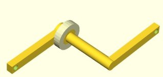
module crankArm() {
difference() {
translate([-10,0,0])
cube(size = [20,150,15], center = false);
translate([0,140,-1])
cylinder(h=17, r=6);
}
}
module outputCoupler() { // Combines the electric and human powered sprag clutches into one
distance = 80;
d1 = 50;
union() {
difference(){
cylinder(h=4, r=65);
translate([0,0,-5])
cylinder(h=10, r=(freewheelOD+slop)/2);
translate([0,0,-10])
for (i = [0:4]) {
translate([sin(360*i/5)*distance, cos(360*i/5)*distance, 0 ])
cylinder(h = 20, r=35);
}
translate([0,0,-10])
for (i = [0:4]) {
translate([sin(360*i/5+36)*d1, cos(360*i/5+36)*d1, 0 ])
cylinder(h = 20, r=8);
}
}
translate([0, 0, -14.5])
hollowShaft( 33, 67, freewheelOD+slop );
}
}
module spindle() {
spindleH = 147;
cylinder(h=spindleH, r=spindleD/2);
cylinder(h=30, r=freewheelID/2);
//Crank arm - right
crankArm();
//Crank arm - left
translate([0,0,132])
rotate(a=[0,0,180])
crankArm();
}
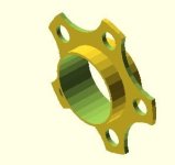
module freewheel() {
color([0.9, 0.9, 0.7, 1])
hollowShaft( 16, freewheelOD, freewheelID+slop );
}
module needleBearing( needleOD, needleH ) {
//http://www.qbcbearings.com/BuyRFQ/NeedleB_ST_OE_M.htm
//Heights: 10, 12, 16, 20
color([0.1, 0.2, 0.8, 1])
hollowShaft( needleH, needleOD, spindleD+slop );
}
module powerShaft() {
translate([0,0,30])
color([0.7, 0.3, 0.5, 1]) {
translate([0,0,47])
hollowShaft( 10+slop, 130,freewheelID );
hollowShaft( 57, freewheelID, needleOD );
}
}
/*
* Cutaway effect for the drawing
*/
module cutaway() {
cutR = 40;
translate([0,cutR/2+10,-slop])
cylinder(h=200, r=cutR/2);
}
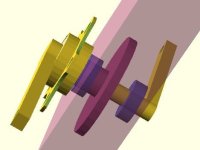
/*
* Building the main picture
*/
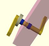
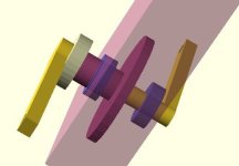
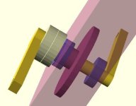
translate([-90,30,50])
rotate(a=[45, 45, 0])
difference() {
union() {
// Off the shelf trials crank plus freewheel
translate([0,0,14])
freewheel();
spindle();
//Off the shelf neede bearings
translate([0,0,71])
needleBearing( needleOD, 16);
translate([0,0,30])
needleBearing( needleOD, 16);
powerShaft() ;
//right side bearing
translate([0,0,49])
color([0.3, 0.3, 0.7, 0.9])
hollowShaft( 16, 50, 22+slop );
//Left side bearing
translate([0,0,110])
color([0.3, 0.3, 0.7, 0.9])
hollowShaft( 16, 50, 22+slop );
translate([0,0,30+slop])
freewheel();
translate([0,0,28])
outputCoupler();
//Drive Shaft
color([0.7, 0.3, 0.5, 1]) {
translate([100,-20,48])
cylinder(h=79, r=12);
translate([150,-40,48])
cylinder(h=79, r=18);
}
//Belt
color([0, 0, 0, 1]) {
translate([0,-65,78])
rotate(a=[0,00,2.5])
cube(size = [156,5,8], center = false);
translate([98,-32.5,78])
rotate(a=[0,00,7])
cube(size = [55,5,8], center = false);
translate([57,20,78])
rotate(a=[0,0,-55])
cube(size = [55,5,8], center = false);
}
//Bike Frame
color([0.7, 0.3, 0.5, 0.5])
difference() {
translate([-80,-80,50])
cube(size = [300,160,75], center = false);
translate([-81,-70,60])
cube(size = [310,140,55], center = false); }
}
// cutaway();
}

 Hello ES!