
DrkAngel
1 GW
WARNING! - DANGER!
There seems to be a cadre of ES member who feel most eBikers are totally ignorant of electricity and its dangers.
Unless you understand electricity, its theory and dangers ... do not read this thread!

Ultimate lightweight charger! ... ?
Experimental!! ... hypothetical!
120V AC power outlet, power cord and a bridge rectifier will output "slightly rough*", up to 20A of 108V DC.
(108V DC output based on 120V APC brand UPS protected-regulated 120V)
This is optimal for charging 26s (96.2V) LiCo (4.15V per cell) or 30s (96V) LiFe (3.60V per cell).
120V AC >>> 108V DC observed through multiple sizes and types of bridge rectifiers , (1A - 30A.)
But some alternate samples might vary, test to confirm!
15A AC outlet provides ≤1500w charger at ~≥90% efficiency.
20A AC outlet provides ≤2000w charger at ~≥90% efficiency.
Requires AC power cord and ≥20A bridge rectifier (Available for ≥$2)
Current regulation regulated by breaker, batteries charge C capacity, BMS or other?
Gauge and length of AC wire could "trim" current?
All charge voltages are based on 120V.
115 or 110V might necessitate alternate cell count. eg. s26-29 AC rectified charger + 1s-4s charger
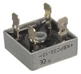
30A bridge rectifier

* Do not add capacitor to smooth DC current!
Might produce an initial, damaging, surge of ~170V !!!
I've been building DC led lighting using rectified AC >>> DC through LEDs in series.
WARNING! in case you didn't know Electricity is dangerous! ... to placate the fear mongers ...
See also - 500w bulk charger
MeanWell S-150-(12-24) + any generic S-350-48 MeanWell clone
There seems to be a cadre of ES member who feel most eBikers are totally ignorant of electricity and its dangers.
Unless you understand electricity, its theory and dangers ... do not read this thread!
Ultimate lightweight charger! ... ?
Experimental!! ... hypothetical!
120V AC power outlet, power cord and a bridge rectifier will output "slightly rough*", up to 20A of 108V DC.
(108V DC output based on 120V APC brand UPS protected-regulated 120V)
This is optimal for charging 26s (96.2V) LiCo (4.15V per cell) or 30s (96V) LiFe (3.60V per cell).
120V AC >>> 108V DC observed through multiple sizes and types of bridge rectifiers , (1A - 30A.)
But some alternate samples might vary, test to confirm!
15A AC outlet provides ≤1500w charger at ~≥90% efficiency.
20A AC outlet provides ≤2000w charger at ~≥90% efficiency.
Requires AC power cord and ≥20A bridge rectifier (Available for ≥$2)
Current regulation regulated by breaker, batteries charge C capacity, BMS or other?
Gauge and length of AC wire could "trim" current?
All charge voltages are based on 120V.
115 or 110V might necessitate alternate cell count. eg. s26-29 AC rectified charger + 1s-4s charger
30A bridge rectifier
* Do not add capacitor to smooth DC current!
Might produce an initial, damaging, surge of ~170V !!!
I've been building DC led lighting using rectified AC >>> DC through LEDs in series.
WARNING! in case you didn't know Electricity is dangerous! ... to placate the fear mongers ...
See also - 500w bulk charger
MeanWell S-150-(12-24) + any generic S-350-48 MeanWell clone
") ... kinda like the "wow, I found a great way to charge my iPhone in the microwave in only 1 min!" and then you see the people who tried it ...
... kinda like the "wow, I found a great way to charge my iPhone in the microwave in only 1 min!" and then you see the people who tried it ...