Making a through hole in a bikes head tube

ntr

1 mW
Joined
Oct 14, 2015
Messages
16
Location
Netherlands
First of all, thanks for all the information on the forum, its been a great resource so far.

I would like to hear your opinion about making two through holes in a bikes head tube.
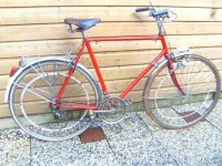
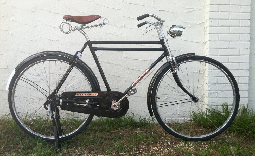
A little background first. I'm starting with my first conversion, most of the parts I need are ordered last week. The bike is a kind of sport bike from the 70's, and I want to keep it look as much as original as posible. So I want to put most of the batteries inside the frame tubes, just like the (canceled) Maxwell EP0 kickstarter project or the Triebflüge on this forum. To get the batteries in the I need to gain access to the top tube and the down tube. The best way I found is by make two holes throug the head tube in line with the top tube and down tube, so I can get the batteries in from the front.
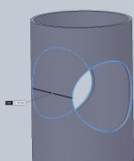
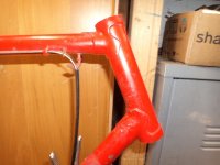
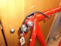
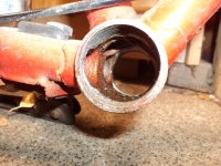
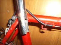
The head tube has an outer diameter of about 31,4 mm and a wall thickness of 1 mm. Lugs are about 1,5 mm thick. The holes will be about 22 mm in diameter. This will take away half of the perimeter surface of the tube at his max. Below a few picture to illustrate.

I design the bike for a max. speed of 25 km/h (15.5 mph) to keep it street legal, and i will not go off-road with it. What do you think? Is it wise to do this or will it weaken the head tube to much? I'm not a mechanical engineer, and I don't think I can make any reliable calculations.
Good arguments will be highly appreciated. Thanks!
 

Attachments

  • _85_003.JPG
    _85_003.JPG
    103.6 KB · Views: 2,284
  • head tube 2.JPG
    head tube 2.JPG
    22.4 KB · Views: 2,284
  • DSC02969.jpg
    DSC02969.jpg
    72.8 KB · Views: 2,284
Going in thru the head tube would definitely require reinforcement. Why not get to the top tube from the rear, and the seat tube clamp would allow hiding anything necessary, and go through the bottom bracket to access the downtube? Are you planning on using the seat tube as well? I'm thinking you want at least 21 18650 cells for 24V with 3 in parallel. Do you have the 1.4m or so of tubing required?
 
Two large Water Bottles would look natural, and would be allot easier to do,
one on the seat tube and the other on the down tube. just cut out the bottom of the water bottles, or split them in half then glue them
back together again. All you/anyone would see is small wires coming out of the bottom of each bottle.
 
Don't do it. If there were any extra beef on a traditional frame like that, well... it wouldn't still be there.

Bore it out and it will break.
 
Thanks for all the sugestions.

The battery setup will be 10S3P. I can fit 24 cells in the tubes if I use all the three main tubes. Maybe even 27 if i'm lucky. The rest of the cells wil go into a water bottle together with the controller and BMS. Putting all batteries in a second bottle is an option, but thats plan B.

I will use the seat tube as well. I can not find a way to get the cells in from the side of the seat tube. The clamp is in the way. Besides that, the wiring from the top tube will come out on that side, they have to go through the seatpost as well, so i am already making concessions on the strength on that side.

Getting into the downtube from the bottom racket is a good option, I'll look into that. There have to be a hole for the wiring anyway. That will leave only on hole in the head tube for the top tube, I think the lugs will be capable to deal with the forces enough.

I got the idea of reinforcing the head tube with an extra tube inside. The inner diameter of the head tube is 29.4 mm. The outer diameter of the steerer tube is 25.4 mm. So if I fit a 29mm OD / 26mm ID tube in the head tube it wil give extra strength. I'll have to make some gaps on one side to be able to get the races of the bearings out.

@ cwah:
I don't understand where I can use these rivet nuts for?
 

Attachments

  • DSC02972.JPG
    DSC02972.JPG
    108.1 KB · Views: 1,393
  • DSC02977.JPG
    DSC02977.JPG
    147.3 KB · Views: 1,393
  • DSC02980.JPG
    DSC02980.JPG
    120.4 KB · Views: 1,393
Head tube failures are the WORST possible failures you can experience on a bike.
You almost guarantee facial reconstruction futures when you mess with that area.
Please consider other options....like a fake Tire Pump or Water Bottle...something safe that preserves the beautiful lines of that frame.
I love lugs...miss them.
 
What if you make a fake top tube to put the batteries in?
photo-1.jpg
 
Dat word nog een flinke klus om alles netjes en goed te krijgen maar het zou wel mooi zijn.
Denk dat het toch gaat tegenvallen...maar je kan het proberen natuurlijk :wink:

Zou zelf voor een mooi leder oldskool frame tas gaan om je accu/bms/controller in te doen,staat wel netjes en
retro bij deze fiets denk ik.
 
OK, I reconsider about using the top tube. Only the seat tube and down tube may be enough space. Nice thougth for the extra top tube Tamaranchorider. It is a nice solution, but more for a transport bike or something. A frame bag as Joachim suggest is something to consider. I have a nice tire pump that goes under the top tube, but it is hard to hide the wirering from there.
 
ntr said:
OK, I reconsider about using the top tube. Only the seat tube and down tube may be enough space.

How do you expect to access the down tube without the same kind of problem? Both ends of the down tube are high stress areas, and the most frequent places for cracks to develop in undamaged frames.

If you build your own frame, you can build in the kind of beefed-up areas and/or access ports that an in-the-frame battery pack will require.
 
If there was enough extra metal in the bike so that it would be strong enough once it was removed to make a hole, it would already have been removed in the design to make the frame lighter. A small hole for a wire might be doable, but a large enough hole to accommodate a battery would compromise the frame's integrity. Your idea sounds awesome, but would be a death trap on this frame.

The alternative is to build up your own frame with thick walled tube that would be strong enough even with the holes.
 
Not a good way to mount batteries on a bike IMO.

You could add a tube like it was suggested; or mount batteries on, under or even each side of a frame tube... You'd better build to be able to access or take the battery off the bike easily, avoiding weakening the bike's strength and stiffness.
 
Chalo said:
ntr said:
OK, I reconsider about using the top tube. Only the seat tube and down tube may be enough space.

How do you expect to access the down tube without the same kind of problem? Both ends of the down tube are high stress areas, and the most frequent places for cracks to develop in undamaged frames.

If you build your own frame, you can build in the kind of beefed-up areas and/or access ports that an in-the-frame battery pack will require.

Chalo,
Don't you think he could go in through the BB to access the down tube with just a straight hole in line with the tube. It would only need to be a bit more than 20mm in diameter. Worst case it would be the easiest spot to hide reinforcing material. The same seems possible by accessing the top tube from the rear, and a bit of custom work on a seat tube clamp could also reinforce that area unseen.
 
The OD of the head tube on that bicycle should be 31.8mm. You should be able to make a 20mm hole (large enough to fit an 18650 battery into) there or into the bottom bracket shell. Neither of those is an awesome option, but it's better than any other option for hiding batteries in the frame. It is common for BB shells to be carved out quite aggressively at the bottom.

10 18650 batteries would be 500mm long, which will fit into most downtubes. You'll still need to hide another string of batteries somewhere, because a 10S1P battery isn't really enough. You'll also need to figure out a way to suspend the battery so that it doesn't slide down and hit the bottom bracket.

You won't be able to fit two strings of 18650 batteries into the downtube. The Faraday has an oversized downtube, and I assume that allows them to fit a 2P battery.

Another option to consider is that you can fit a 10S2P battery pack into a handlebar bag or saddlebag. Both of these are pretty discrete locations and leave the bike looking fairly stock, and don't require any frame modifications.

The hard part with making a DIY e-bike look discrete is hiding the mess of wires. If you want to spend effort engineering a nice solution you need to figure out how to make the CAv3 a lot smaller (not too hard, the logic board is way smaller than the display board), hide the motor controller somewhere nice, and run the wiring between the battery, motor, controller, CAv3, and bottom bracket discretely. It would be great if there was a CAv3-like device integrated into a 15A controller for these bikes.
 
Ten 18650's aren't 500mm long. 18 is the approximate diameter of the cell, and 65mm is the approximate length. 10 will be significantly longer than 650mm though. That's because the connection takes up space, since even at your relatively low current needs a pressure connection will not work.

I've done some end-to-end batteries in series before, and you need to plan the series connection well. eg If you tab weld, then you're doing the welding with the batteries side by side, and then have to make a fold in the tab perfectly for the cells to line up end-to-end perfectly. Plus you have to consider the corners of the tab that will stick out.
 
John in CR said:
Chalo said:
Both ends of the down tube are high stress areas, and the most frequent places for cracks to develop in undamaged frames.

If you build your own frame, you can build in the kind of beefed-up areas and/or access ports that an in-the-frame battery pack will require.

Chalo,
Don't you think he could go in through the BB to access the down tube with just a straight hole in line with the tube. It would only need to be a bit more than 20mm in diameter. Worst case it would be the easiest spot to hide reinforcing material. The same seems possible by accessing the top tube from the rear, and a bit of custom work on a seat tube clamp could also reinforce that area unseen.

Like so many things, it just depends. How thick is the bottom bracket shell? How much of the joints to the chainstays will be cut away in the process? How do you protect the cells from abrasion and vibration damage without cutting a bigger hole for both the cells and their protective material?

These factors can be addressed if the frame is built especially for the purpose. But as I and others have pointed out, this is a highly iterated frame we're discussing, with no significant extra material on it beyond what's necessary.

The first e-bike I ever built, in the late '90s before e-bikes interested me personally, had a battery pack stuffed into the frame boom, which was made of a section of aluminum sailboat mast. True to the time period, the battery was three sticks of ten Sanyo D cell Nicads in series for a nominal 36v 5Ah. The opening to load them was located below the bottom bracket shell.

I remember watching my buddy freak out when his pack ran away and started smoldering inside the frame. He had that sucker ripped out of there in seconds. I think that's a consideration with this frame even with the better battery options available today.
 
I still like the idea of getting into the tubes through the head tube and reinforce the head tube with an extra tube inside. I totaly agree that this it not a rock solid frame, and I have no idea if that extra reinforcement is enough. But the lugs are left intact, so the connections of the down and top tube to the head tube are still OK. The fork tube will put lateral load on the bottom bearing and the top bearing, which are both inforced with the lugs. As far as I can imagine the head tube can never fail fatal this way. In the worst case it wil have some cracks or will deform, but the extra tube will hold it all together. It would be a shame if it deforms irreversible, but worth the try I think. I will notice quick enough if the steering has resistans because of deformation.

The bottom bracket has a stronger contruction because of all the luggs on it, but it looks less reliable to make a big hole in there.

I've search for FEM analysis on bicycle frames, but I have no idea how to translate that information to someting meaningfull for my situation. for example:

http://training.altairuniversity.com/analysis/structural/linear-static-analysis/conceptual-design-of-a-bicycle-frame/
https://productdes.wordpress.com/2013/11/30/parametric-finite-element-analysis-of-bicycle-frame-stiffness/

Obviously riding through a puthole will give other higher loads on the head tube than this static analysis shows.


In the mean time I'm looking for alternatives. This may be a nice option:
http://www.brooksengland.com/catalogue-and-shop/bags/cycle+bags+%26+accoutrements/Challenge+Tool+Bag/

That will fit 9 cells and the BMS. Ten cells in the seat tube and 11 in the water bottle must be possible.


And a little off topic, but for your information:
The battery setup will be 10S3P out of Sanyo NCR18650GA cells. Top tube is 530mm, down tube is 590 mm and seat tube is 660 mm including the seatpost. I can fit 24 cells in the tubes if I use all the three main tubes, but if the cells are soldered close enough maybe more. I have cells with U-tabs that I'm going to solder side by side as JohninCR suggest, and fold them hopefully in a perfectly straight line. For the balancing wires I use flat ribbon cable that is 1 mm thick with connectors with a 1.27mm pitch so the connectors will be as wide as the ribbon cable. For the main wire + and - I use something like the shielding of a shielded cable that I strip off, and insulate that with shrink tube to get a flat wire. Then shrink tube around the cell + ribbon wire + main wire and I hope to get an overall diameter for the battery of 20 or 20.5mm, so a hole of 21 mm will do, 22m in worst case.

I have a S06S controller from BMSBattery which is fairly small. I use an S-LCD3 display for initial testing, but I'm gonna replace that with an microcontroller that emulates the S-LCD3 by recording the data from the S-LCD3, store that in EEPROM and send it to the controller if the display is disconnected. That microcontroller is really small. I have no plans for a Cycle analyst. I need a PAS sensor too to keep it road legal, I will try to hide it inside the bottom bracket, but thats an other challenge. Wiring for the motor, speed sensor and brake sensor are other things I will have to find a nice solution for.
 
Back
Top