Micro Lebowski Controller - DIY 3kw

to measure the inductance correctly will be virtually impossible, you need to distinguish between L_d and L_q. You would need to disconnect the three windings completely, measure all 3 inductances and do some math...

to start with loads sensored should be no problem....
 
Lebowski said:
to start with loads sensored should be no problem....
of course not ;) i just was describing the problems i have to make it easier for you to identitfy the issues and see if your assumptions regarding inductance make sense for the failure scenarios i have.
 
The MAC I was testing on in Brisbane was 150uH.. Izeman what's yours?

So... what do we do? you say play with the Inductance measurement. how much variability are you expecting? for example if I get 150uH as my nominal inductance what is the acceptable range of adjustment going to be? Will it be somewhere like 150uH +/- 3uH or will we need to fiddle in the +/- 1uH range? can we do this?

I can't test on a MAC any more, still contemplating if I want to get an Ezee motor which is quite similar.

Andy
 
Animalector said:
The MAC I was testing on in Brisbane was 150uH.. Izeman what's yours?

So... what do we do? you say play with the Inductance measurement. how much variability are you expecting? for example if I get 150uH as my nominal inductance what is the acceptable range of adjustment going to be? Will it be somewhere like 150uH +/- 3uH or will we need to fiddle in the +/- 1uH range? can we do this?

I can't test on a MAC any more, still contemplating if I want to get an Ezee motor which is quite similar.

Andy

I think Izemans MAC was 80 to 90 uH, but I think he has an 8t...

Well, worst case L_d and L_q are so different one is 0, in which case the controller probably sees only half the inductance. So, from 150uH I would go up in about 5% steps (8uH) and then for every step try out the controller under load. To do this you need to manually edit the HEX file (for v2.30) or use the % setting in v2.40 ..
 
Lebowski said:
[I think Izemans MAC was 80 to 90 uH, but I think he has an 8t...

Well, worst case L_d and L_q are so different one is 0, in which case the controller probably sees only half the inductance. So, from 150uH I would go up in about 5% steps (8uH) and then for every step try out the controller under load. To do this you need to manually edit the HEX file (for v2.30) or use the % setting in v2.40 ..
correct. it should be an 8T. but i have 3 MACs and for sure they are different windings. so i will have to try which one is installed at the bike right now.
so when i get the controller back, i'll do a complete new setup with autocomplete, change NOTHING, but try playing with this inductance percentage setting setting it to 105%, 110% etc ... or lower it respectively?!
any idea why the controller got so hot compared to the kelly? could that be the wrong inductance setting putting too much stress on the FETs?
 
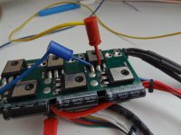
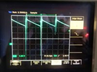
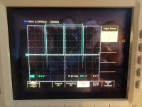
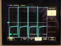
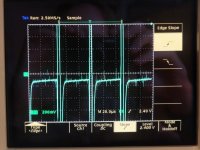
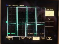
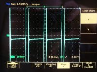
Just had some funny measurement results when putting 10A through the controller.

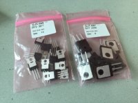
2 low side FETs are 20 mOhm (B and Y), 1 is 10 mOhm (G)
3 high side FETs are 10 mOhm (B and Y), 1 is 20 mOhm (G)

a 4468 should be around 2 mOhm....

in the same setup a 4115 measures to a bit less than 10 mOhm, as it should.

I used kelvin contact type measurements, so with the probe staight at the legs where they enter the FET housing.
For the high side I used a 10s LiPo battery, for the low side my 65V lab supply.

View attachment 9
DSC01785.jpg
DSC01786.jpg
DSC01788.jpg
DSC01789.jpg
View attachment 4
DSC01791.jpg
DSC01792.jpg
DSC01793.jpg
DSC01794.jpg
 
Lebowski said:
izeman said:
f*ck utsource. so i guess not matter what inductance the motor has those FETs are crap and the extremely high ir explains the extreme heating.
yep, I was looking for the cause of this as the inductance did not really explain it for me...
BAS I REALLY OWE YOU SOMETHING! i couldn't have done the measurement, and w/o your help i would have played around with different settings, and still not make it work. i think this will be an important information for andy as well, as he will need to replace the FETs as well.
sorry for the stupid question: does the high internal resistance also explain the conk out? i guess the resistance being high is bad, but the worse part is all being different?
 
Tja this is now the big question, i don't know. I still like my inductance explanation, but on the other hand about 1V drop across a FET is not insignificant (especially keeping the low battery voltage of only 48V in mind)
 
And the difference between them can't help either. nice work Bas. Thanks for looking into it. I really should get a credit from utsource and site this thread as evidence. Maybe I can get some new current sensors which seem to be ok from them...
 
Animalector said:
Maybe I can get some new current sensors which seem to be ok from them...
i hope they are ok. at least they gave correct results when i measured them. and they are quite easy to measure. i hope not everything from them is bad.
i ordered some new 3077 from reichelt.de as well in case i need to replace some FETs from my regular infineon controllers or need some FETs for the inrush limiter. they are 2€ a piece only.
 
So how are you planning to swap the fets. Just cut the legs and solder from the bottom? I had bent the legs along the track on the inner surface so it'd be a pain to fully desolder them now that you have it all assembled
 
Animalector said:
So how are you planning to swap the fets. Just cut the legs and solder from the bottom? I had bent the legs along the track on the inner surface so it'd be a pain to fully desolder them now that you have it all assembled
it will be a MASSIVE pita to swap them. especially as i used A LOT of solder to fix them and make heat bridges ... i will try to use a pump to remove as much solder as possible, than braided desolder wire and then cut the legs with a dremel. cutting them with a side cutter may put too much stress on the board and remove pcb traces. then heat the remaining feet with a 80w iron with a 5mm thick soldering tip ad 450C and pull them out with pliers. i hope that works, because otherwise i will have to try to seperate the two boards which will be next to impossible as those 6mm standoffs i made transfer heat exceptionally well.
 
Next question. Want me to send you new boards? Can supply the same style as that and I might finish off my new layout and can send you one of those as well. Thoughts?
That way you can be a bit ruthless with the circuit board
 
Animalector said:
Next question. Want me to send you new boards? Can supply the same style as that and I might finish off my new layout and can send you one of those as well. Thoughts?
That way you can be a bit ruthless with the circuit board
well. maybe having a second cicuit board would be helpful. the 3 stacked boards as is are a perfect fit for my case now. i already drilled all holes etc so i would not want to change that. and i don't know what the benefit of the new board would be?!
but i'd be interested to see a new board/controller of course :)
 
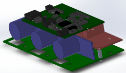
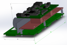
Ok, so here's the newer version, jut roughed up in CAD. i export the PCD file as a DXF and import it into the CAD package. so I know that the PCB's I get will fit where they are supposed to.

I like this one better because,
easier wiring FET board to driver board
better layout of CAPs
Shorter / more efficient layout of high current paths
I can use my original CPU board.
I can unscrew the driver board and fold it over to access the top of the FET board (easier assembly)

Lessons learned from last job..
many board-to-board interconnects makes assembly difficult,
bus interconnects were not practical. needed an alternative solution - now a BUS PCB... +VBat one side, 0V the other.
not able to access tops of FETs for mounting once the PCB's were assembled.
BUY COMPONENTS FROM TOP NAME SUPPLIERS

Comments welcome..
Lebowski V2_3 (Custom).png
Lebowski V2_2 (Custom).png

Andy
 
There's a higher current version of the 15v supply. I think it's a drop in replacement. I might look into that see if the parts fit. I also might make a few holes for zip ties on the battery cable and phase wires To secure them. I need part numbers for the caps I found good ones but didn't write the number down then I'm done. Need to order stuff this financial year so I can claim some of it back on tax
 
big physical difference. I was amazed at the weight of the controller once it was assembled..

anyways been busy so I haven't done anything with mine but model the new boards. i'll buy the boards this month though. any suggestions before I do? anything that'll make it easier to assemble?

Andy
 
Animalector said:
big physical difference. I was amazed at the weight of the controller once it was assembled..

anyways been busy so I haven't done anything with mine but model the new boards. i'll buy the boards this month though. any suggestions before I do? anything that'll make it easier to assemble?

Andy
did you add the resistor and connector for the temp sensors ?
 
Back
Top