The State of Wye-Delta Switching

grindz145

1 MW
Joined
Apr 7, 2009
Messages
2,962
Location
Rochester NY
A primer:

When using a hub-motor, at a given voltage, there is a maximum speed, which is based on the kV of the motor, which is related to the turns ratio. A way that several members on the forum have achieved a higher top speed is through Wye-Delta Switching.

What does that mean?
View attachment Basic Theory.JPG

So you can effectively change the winding characteristic of the motor to allow for a higher top-speed. However, if you simply hardwire the motor into Delta, you sacrifice low end toque (that you need) and ultimately efficiency. So a solution that a few members on the forum have experimented with is to switch from Wye-Delta on the fly.

View attachment Relay Switching.JPG
Yeah, I know, my drawings blow...

It recently came back to my attention when Hyena posted one of the hub motors that he modded in the for-sale section.

View attachment star-delta_relays.jpg
http://www.endless-sphere.com/forums/viewtopic.php?f=9&t=23079&p=362884#p362884
http://www.endless-sphere.com/forums/viewtopic.php?f=6&t=14954&start=150

Other members such as Doctorbass have tried this as well with pretty good results.

There are a few issues to be aware of:
1. You need a baller-ass controller. Once you lower the phase impedance, current control is much harder for the controller.
2. Relays that fit in hubmotors will probably not be rated for the current you need to push through them, which will ultimately lead to unreliability and failure. (though some have done pretty good with reliability)
3. Most relays that are being used are not rated for ebike voltages either. This can be mitigated for the most part, by making sure that the relay is only switched when the throttle is closed (IE no current is flowing to the motor).
4. The wiring is complex and you do need to feed a couple of extra signal wires through the axle to power the relays.
5. Doing 45+mph on most bicycle frames is for OGs only.


I proposed using a mosfets to perform the switching, Ill include that discussion in another post.

P.S.: just found the old thread with better drawings and more detail :roll: 8) : http://www.endless-sphere.com/forums/viewtopic.php?f=2&t=9215&hilit=doctorbass+wye+delta+switching
 
Just a few things to add.

Torque capability between both Delta and Wye, both the saturation torque, the torque per amount of power going into the hub at the same speed, and continuous torque capability (actually about 2% lower for delta) area all the same for Delta or Wye.

This is because the torque handling of a motor is determined by the copper fill, the winding methods/turns etc can all change the KV which changes the torque per amp the motor produces, but the torque capabilities of the motor remain unchanged unless the amount of copper in the slots changes.

The reason for making a delta-wye switch or series parallel switch is to enable less phase current burden on a controller while operating at low speeds. In other words, it lets you run a weaker controller than would be capable of running reliably with that high of KV wind while at low RPMs, because when you're at low RPMs, you can operate in Wye and place only ~59% of the phase current burden on the fets of the controller for a given amount of torque produced. Note! This has no effect on the battery current per amount of torque produced at a given motor RPM, only on the phase current.

The downside to Delta is recirculating currents. A delta motor's winding make a loop. When the magnets move past the teeth (and very much-so in motors with skewed teeth), you end up creating current ripples in this loop from magnetic induction (generating BEMF).

For this reason, a delta can never have the efficiency of an equal KV wind with a Wye pattern.


So, the function of a delta-wye, or a series-parallel system both accomplish the same goal, enabling a controller that would otherwise blow starting from 0rpm with that high of a KV motor to survive.
 
Thanks LFP. Eddy currents are what kills Deltas efficiency and ultimately reduces motor torque...

More on the FET switching discussion:

A summary of the good:
-Fits nicely inside the motor
-Low Impedance

A summary of the bad:
-Huge losses just from body diodes, without creating another H bridge.(Not viable)
-Driver isolation would be difficult
-Signal isolation important as well
-Another thermal management problem - adds more heat to the motor
 
grindz145 said:
Thanks LFP. Eddy currents are what kills Deltas efficiency and ultimately reduces motor torque...


Recirculating currents. Not eddy currents (eddy currents should be equal between delta or wye).

Not trying to be a dick :) Just want to make sure if we're going to make a resource about something that we get the names right.
 
liveforphysics said:
grindz145 said:
Thanks LFP. Eddy currents are what kills Deltas efficiency and ultimately reduces motor torque...


Recirculating currents. Not eddy currents (eddy currents should be equal between delta or wye).

Not trying to be a dick :) Just want to make sure if we're going to make a resource about something that we get the names right.

Thanks :twisted: Pardon my ignorance, whats the difference between eddy and recirculating currents? Untill now, I've used the two interchangeably.
 
Eddy currents are caused by the potential created across a conductive material when a magnetic field moves in relation to it (flux lines cutting/scrapping through it is a fair visual). This induced voltage is multiplied by the resistance of the material to create a current that is locally absorbed by I^2*R losses as heat in the material. An example would be stator laminations. The reason you want them thin (and insulated from another) on the perpendicular axis to the direction of the flux motion is to minimize the distance across which a potential can be induced, which minimizes the amount of potential, and minimizes the amount of current shorting inside them as heat.


Recirculating currents (sometimes called winding circulating current, or a few other names) are due to the inherent imbalance of induced potential inside the conductor loop created by the winding termination. This creates an inherent voltage imbalance between one side of the loop to the other, and since they share termination points (hence making the loop), they have internal closed system current flow inside this loop that changes every time the motor has a change in magnet-tooth position. Depending on the motor wind/design, this current can change from being so extremely mild it would be almost impossible to notice in a practical application (like under <1% efficiency) to something in an extreme effect that makes 10-15% difference in efficiency (but you would pretty much have to optimize a motor around maximizing circulating current losses to get it that bad.)


Ultimately though, a Wye termination will never have this internal current loop, so when possible (it's more labor intensive to wind a Wye pattern than delta due to delta not needing a connection), always choose wye in the KV range you desire.
 
Jeezis Luke, can you slow that train down for the cybernetically unenhanced? I had to read that, walk around a bit, then read it twice more.

Katou
 
Is this system also going to be programmable so it auto-switches or is it still just done with a switch on the handlebars.

I was just going to use a switch on mine but something that does it for me would be sweet.

I don't have the option of mounting inside my geared motors as there is just no room. I had planned on running 6 phase wires out to some relays I have that should work OK at the low power levels I need.

Gary
 
GrayKard said:
Is this system also going to be programmable so it auto-switches or is it still just done with a switch on the handlebars.

I was just going to use a switch on mine but something that does it for me would be sweet.

I don't have the option of mounting inside my geared motors as there is just no room. I had planned on running 6 phase wires out to some relays I have that should work OK at the low power levels I need.

Gary

Rather then putting the effort into the mosfet switching or something else along those lines, I think my course of action will be to pull all 6 wires out of the axle, and switch with a larger, high-quality contactor. It will be bigger and more reliable, but moreover if it does fail, I can fix it without removing the motor. I want to be able to do hundreds of miles on my bike and be able to deal with whatever I have to without needing to be in the lab to do it.

Going along with that and what you mentioned, I think what Ill focus my efforts on is to make a circuit that is quickshifter, which will pull the throttle low for 250ms or so and switch the contactor by a pushbutton. Though some of the guys (doctorbass) have had success switching under throttle, It's asking for it with lower voltage switching devices. I'm actually amazed at how reliable they are, but I want it to be operator-proof for the most part. Plus it will feel alot nicer:)

p.s. I wouldn't necessarily have it auto-switch due strictly to wheel speed, though I've considered it. There are many cases when you just want to max out the kV and accept the motor efficiency running in Wye. Like many that have tried it, I'd use it more of a "turbo" or "pass" switch I imagine.
 
katou said:
Jeezis Luke, can you slow that train down for the cybernetically unenhanced? I had to read that, walk around a bit, then read it twice more.

Katou

He's good at that 8) . There are other forums just for bikeporn, but I like the cerebral stimulation myself :lol: .
 
I like where you are going with this. Reliability and ease of repair are high on my list too.

As to the auto or manual shift it would be nice to have both options. Say an auto setting that shifts by some criteria for commuting, and a manual for offroad or for odd road conditions.

I can make suggestions on features but my circuit building knowledge ends at a C cell battery, two pieces of wire and a light bulb, so I will be no help in that department. :oops:
 
Has anyone made any progress on this RELAY switch from DELTA TO STAR ?

Do you need a special controller to run this RELAY switch ?

i have a motor that standard runs on DELTA, would it also be easily be able to be switched to run STAR if star uses less CURRENt ?

How do i tell if my brushless DC motor is winded STAR or delta ?
 
liveforphysics said:
Eddy currents are caused by the potential created across a conductive material when a magnetic field moves in relation to it (flux lines cutting/scrapping through it is a fair visual). This induced voltage is multiplied by the resistance of the material to create a current that is locally absorbed by I^2*R losses as heat in the material. An example would be stator laminations. The reason you want them thin (and insulated from another) on the perpendicular axis to the direction of the flux motion is to minimize the distance across which a potential can be induced, which minimizes the amount of potential, and minimizes the amount of current shorting inside them as heat.


Recirculating currents (sometimes called winding circulating current, or a few other names) are due to the inherent imbalance of induced potential inside the conductor loop created by the winding termination. This creates an inherent voltage imbalance between one side of the loop to the other, and since they share termination points (hence making the loop), they have internal closed system current flow inside this loop that changes every time the motor has a change in magnet-tooth position. Depending on the motor wind/design, this current can change from being so extremely mild it would be almost impossible to notice in a practical application (like under <1% efficiency) to something in an extreme effect that makes 10-15% difference in efficiency (but you would pretty much have to optimize a motor around maximizing circulating current losses to get it that bad.)

Ultimately though, a Wye termination will never have this internal current loop, so when possible (it's more labor intensive to wind a Wye pattern than delta due to delta not needing a connection), always choose wye in the KV range you desire.

There's another way to get circulating currents in a Delta configuration, and that's with third harmonics. If you draw a vector diagram for the back emfs in a Delta, the vectors from the three windings form a neat triangle and come back to the starting point. The effect Luke described above is when the three vectors are not quite equal and the triangle isn't closed.

But that diagram only applies to the fundamental. Some motors are constructed so that the waveform isn't a pure sine wave and there is a third harmonic. In the vector diagram the third harmonics are in line, not in a triangle, so they will set up a circulating current even if the windings are perfectly balanced.

Nick
 
There's another way to get circulating currents in a Delta configuration, and that's with third harmonics.

Phrased differently, you get a trapezoidal BEMF curve by adding third harmonics to a sine wave. So any motor with a trapezoidal BEMF curve (like many RC motors) should see an efficiency improvement with a wye winding.

Edit: Another useful description.
 
jdb said:
There's another way to get circulating currents in a Delta configuration, and that's with third harmonics.

Phrased differently, you get a trapezoidal BEMF curve by adding third harmonics to a sine wave. So any motor with a trapezoidal BEMF curve (like many RC motors) should see an efficiency improvement with a wye winding.

True. If you search around ES, there are a few threads where peeps have posted scope BEMF waveforms from motors. Sometimes you can see they are not perfect sines and occasionally they are way off.

Nick
 
Here is the waveform every outrunner I've played with has given me. Astro inrunners do a shared-tooth winding thing, and have a distinct 3rd order waveform.
[youtube]lBPknG7oG6U[/youtube]
 
Here is the waveform every outrunner I've played with has given me. shows sinusoidal waveform video

Well, color me surprised and thanks for the data. Does your 'scope have an FFT function or THD (total harmonic distortion) option? Waveforms that look sinusoidal to a Mk1 eyeball can still have quite a bit of harmonic content.
 
Hummina Shadeeba said:
what is the state of the wye-delta switch? is there one commercially available for a three phase motor?

You can only make a magnetic design that produces sinus BEMF when terminated in one or the other, but not both.

Between 2011 and now, mosfets have seen RdsOn be cut in half meaning the best you could achieve for a torque range per amount of controller without using delta/wye switching is already wider than it used to be with it.
 
I understood the benefit of a wye/delta switch being greater efficiency in the motor as you could lower the kv for slow speed torque and start-up in wye and then later increase the kv with delta for higher speed. Are you saying things have changed in this regard?
a sinus bemf...i'm surprised as I'd think it would be related to the teeth and magnet shape and not the termination. but then again so many outrunner motors supposedly don't have a sinus bemf anyway I read.
 
wye/delta switching only reduces the load on the current supply (be that controller or mains) of a motor starting under load. Apart from the relatively minor consequences Luke mentions, the motor doesn't really care how it's windings are terminated - it's still the same amount of copper wound onto the same teeth and the same amp-turns to make a given amount of torque.
 
Hummina Shadeeba said:
I understood the benefit of a wye/delta switch being greater efficiency in the motor as you could lower the kv for slow speed torque and start-up in wye and then later increase the kv with delta for higher speed. Are you saying things have changed in this regard?
a sinus bemf...i'm surprised as I'd think it would be related to the teeth and magnet shape and not the termination. but then again so many outrunner motors supposedly don't have a sinus bemf anyway I read.

You get absolutely no efficiency advantage possible in switching from delta to wye or wye to delta.

The best you can do is Wye in practice due to motor imperfections in delta creating real world recirculation currents in the delta loop (though often this is some tiny fraction of a percent of losses).
 
What about using a motor with a very high kv while going slowly and using high power? Using the grin motor simulator shows this is less efficient. Switching from delta to wye drops the kv to almost half
 
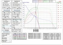
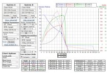
maybe I'm using the simulator wrong but in these pics are a comparison of two systems:

double voltage and half throttle

double kv

the load stays the same for both systems....why the different efficiency?

same but kv.JPGdouble voltage half throttle.JPGthe load stays the same and same rpm and but different efficiency

Assuming the difference in efficiencies here is partially in the motor and not all the esc, which I think is the case I've heard same torque to heat output of a motor regardless of kv but that's assuming optimum situation while with a large load at slow speed it seems differences w the simu and a lower kv more efficient for same power output. So in that way wye is more efficient as it would be a decrease in kv..
It seems efficiency is best when the applied voltage isnt far higher than the back voltage. If not too much power is asked for, meaning not too high of this voltage contrast, the higher kv can get similar efficiency. And the potential to do much higher power but at reduced efficiency.
That's how I understand it. Please clue me in to my misunderstanding!
 
Back
Top