updated 1st post summary:
For the past 5 years, I have been developing sensorless BLDC controllers (HW and SW) based on the PIC18F4431 Microcontroller from Microchip.The initial motivation was to design a high efficiency BLDC controller for solar RC car races, basically a 1kg RC car powered by a 20dm² solar panel. I had to design my own controller because most commercially available solutions were optimised for cost and not flexible or open enough to implement the required power management for a solar vehicle. When you only have 20W of power, any improvement in efficiency counts!
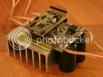
So my 1st generation controller integrates sensorless BLDC control, MPPT for a solar energy source and power management for a supercapacitor or battery buffer. I started the SW development on a stripboard prototype and then, once the basis of my design got stable enough, I designed a small form factor PCB:
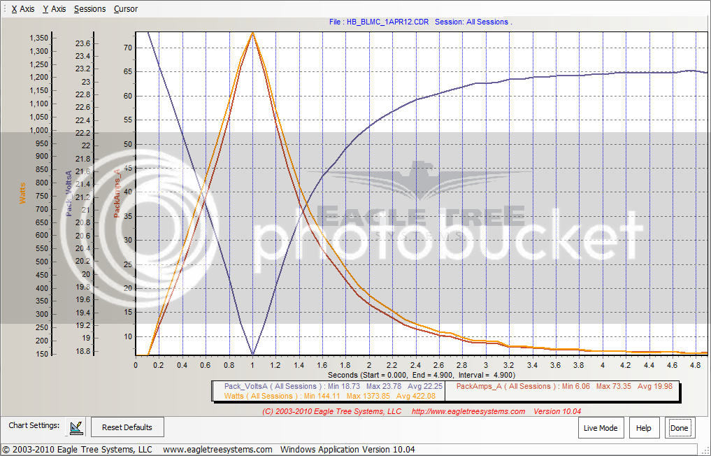
By 2010, I had a fairly robust controller but I was well behind with the design of the rest of the car, so while looking for a partner to build a race and found a RC plane builder who was interested in my controller to build a RC solar plane. I found this new challenge immediately more motivating and moved on from the car to the plane") . The "plane" which is actually a flying wing design successfully flew in 2011 and the developer is still optimizing the mechanical side of it to reduce weight and improve its range. This controller is confirmed to be 10-15% more efficient than controllers commercially available...
. The "plane" which is actually a flying wing design successfully flew in 2011 and the developer is still optimizing the mechanical side of it to reduce weight and improve its range. This controller is confirmed to be 10-15% more efficient than controllers commercially available...
So, when the 2011 winter arrived I found myself without any project and I decided to upgrade the motor on my Goped ESR scooter to brushless to complement my DIY A123 battery pack with custom BMS. As I was browsing the ES forum for motor advise, I found that BLDC controller were a significant factor limiting to use of the brussless motor on DIY EVs! It seems there are very few options that are flexible, low cost and robust enough for the E.V enthusiasts. Also I was disappointed to see that most controller projects that started with the good intention to go open source, didn't for some reason...
Sensorless BLDC control is not complicated but it takes time to get it working well. I think I have a solution that works and so I decided to share it so other DIY-er can design their own controller with limited effort on the SW side. See below for more details on the 1st generation controller.
I'm now working on a 2nd generation controller which is designed specifically for EVs using brushless RC motor with:
- High power continuous handling capability ~2kW
- Low inductance motor support ~50uH (and probably less)
- High torque Sensorless start and drive
- Phase current control
- Regenerative braking
You can follow the development of the 2st generation controller on this same thread
================================================================================================================================
1st generation controller:
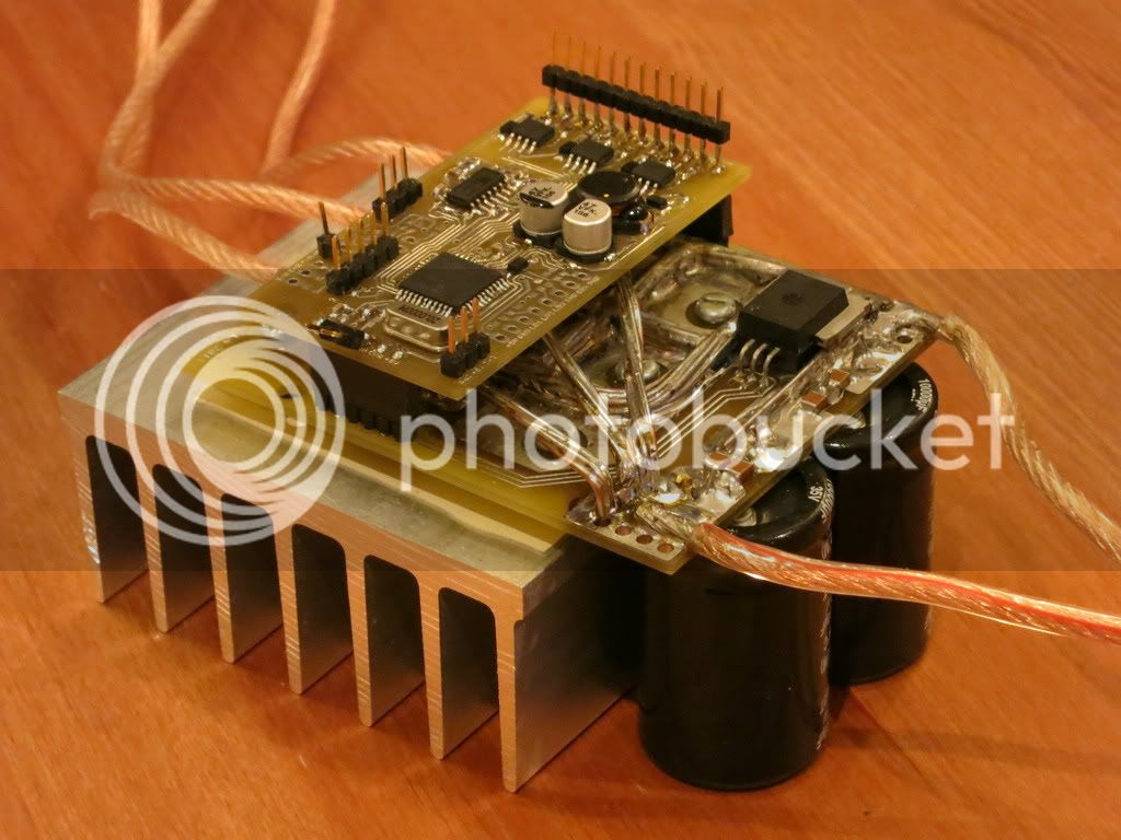
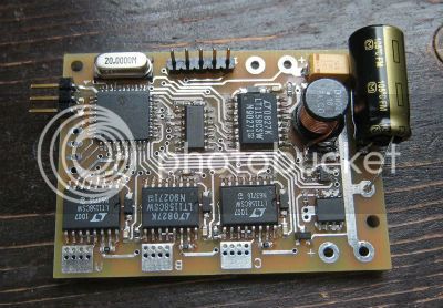
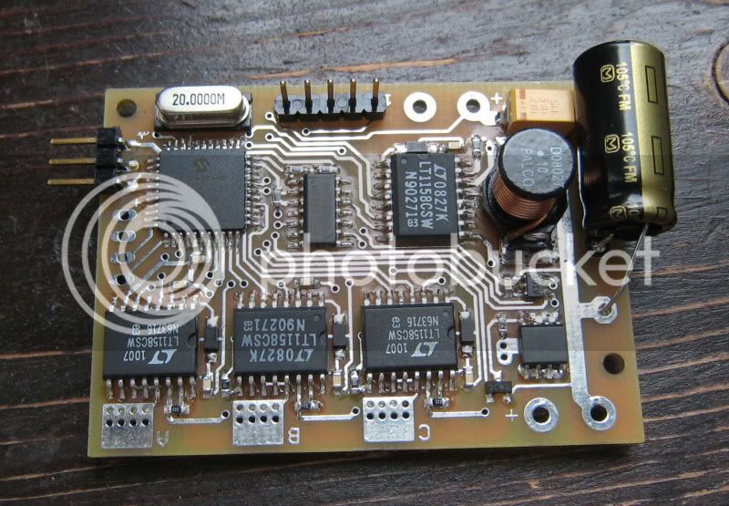
Here is a picture of one of the controllers:
Here is the schematic:
View attachment 1
My 1st generation controller is based around a PIC18F4431 Microcontroller and LT1158 drivers. Provided you are ok with using the same microcontroller and similar drivers (with an enable and PWM input), this design can be scaled up to support relatively high level of power with little effort.
The source code is being release under the Creative Commons Attribution-NonCommercial-ShareAlike 3.0 Unported License (http://creativecommons.org/licenses/by-nc-sa/3.0/).
Here is the source:
Notes:
- I can provide some support on HW and advice on code changes to people designing controller based on my solution, in particular to setup the demag and advance timing.
- This code is ready to be compiled and run. It takes a RC servo style signal as an input, both car and airplane styles are supported. Soft LVC is also supported
- The PWM is set at 20kHz but can easily be changed. The ADCs are fully setup to sample at 800Hz and there is enough processing power to do stuff at that rate.
- The bridge if fully synchronous for efficiency reason. So it could support regenerative braking with the appropriate software. Regen not being worth it on a ~1kg RC car, the software only support braking by shorting the 3phases. This should not be used on a large size EV, as it would quickly burn the motor!
- I will most likely design a high power controller to go brushless on my scooter and I'll try to publish most of my work but that might not happen until next winter now.
- Although limited, there should be enough comments in the code to explain how thinks are working. I will try to answer as many question as possible but I have limited time available and I don't intend to teach the principle of sensorless BLDC control, there is a lot literature out there for that.
- This code is stripped out of all the code related to solar power and battery buffer management which is not really relevant to large size EV (yet). Some references to it however remain in the code, please ignore it.
Laurent
For the past 5 years, I have been developing sensorless BLDC controllers (HW and SW) based on the PIC18F4431 Microcontroller from Microchip.The initial motivation was to design a high efficiency BLDC controller for solar RC car races, basically a 1kg RC car powered by a 20dm² solar panel. I had to design my own controller because most commercially available solutions were optimised for cost and not flexible or open enough to implement the required power management for a solar vehicle. When you only have 20W of power, any improvement in efficiency counts!
So my 1st generation controller integrates sensorless BLDC control, MPPT for a solar energy source and power management for a supercapacitor or battery buffer. I started the SW development on a stripboard prototype and then, once the basis of my design got stable enough, I designed a small form factor PCB:
By 2010, I had a fairly robust controller but I was well behind with the design of the rest of the car, so while looking for a partner to build a race and found a RC plane builder who was interested in my controller to build a RC solar plane. I found this new challenge immediately more motivating and moved on from the car to the plane
. The "plane" which is actually a flying wing design successfully flew in 2011 and the developer is still optimizing the mechanical side of it to reduce weight and improve its range. This controller is confirmed to be 10-15% more efficient than controllers commercially available...So, when the 2011 winter arrived I found myself without any project and I decided to upgrade the motor on my Goped ESR scooter to brushless to complement my DIY A123 battery pack with custom BMS. As I was browsing the ES forum for motor advise, I found that BLDC controller were a significant factor limiting to use of the brussless motor on DIY EVs! It seems there are very few options that are flexible, low cost and robust enough for the E.V enthusiasts. Also I was disappointed to see that most controller projects that started with the good intention to go open source, didn't for some reason...
Sensorless BLDC control is not complicated but it takes time to get it working well. I think I have a solution that works and so I decided to share it so other DIY-er can design their own controller with limited effort on the SW side. See below for more details on the 1st generation controller.
I'm now working on a 2nd generation controller which is designed specifically for EVs using brushless RC motor with:
- High power continuous handling capability ~2kW
- Low inductance motor support ~50uH (and probably less)
- High torque Sensorless start and drive
- Phase current control
- Regenerative braking
You can follow the development of the 2st generation controller on this same thread
================================================================================================================================
1st generation controller:
Here is a picture of one of the controllers:
Here is the schematic:
View attachment 1
My 1st generation controller is based around a PIC18F4431 Microcontroller and LT1158 drivers. Provided you are ok with using the same microcontroller and similar drivers (with an enable and PWM input), this design can be scaled up to support relatively high level of power with little effort.
The source code is being release under the Creative Commons Attribution-NonCommercial-ShareAlike 3.0 Unported License (http://creativecommons.org/licenses/by-nc-sa/3.0/).
Here is the source:
Notes:
- I can provide some support on HW and advice on code changes to people designing controller based on my solution, in particular to setup the demag and advance timing.
- This code is ready to be compiled and run. It takes a RC servo style signal as an input, both car and airplane styles are supported. Soft LVC is also supported
- The PWM is set at 20kHz but can easily be changed. The ADCs are fully setup to sample at 800Hz and there is enough processing power to do stuff at that rate.
- The bridge if fully synchronous for efficiency reason. So it could support regenerative braking with the appropriate software. Regen not being worth it on a ~1kg RC car, the software only support braking by shorting the 3phases. This should not be used on a large size EV, as it would quickly burn the motor!
- I will most likely design a high power controller to go brushless on my scooter and I'll try to publish most of my work but that might not happen until next winter now.
- Although limited, there should be enough comments in the code to explain how thinks are working. I will try to answer as many question as possible but I have limited time available and I don't intend to teach the principle of sensorless BLDC control, there is a lot literature out there for that.
- This code is stripped out of all the code related to solar power and battery buffer management which is not really relevant to large size EV (yet). Some references to it however remain in the code, please ignore it.
Laurent