Machining a Brushless motor design

magudaman

10 kW
Joined
Jul 10, 2007
Messages
695
Location
Bay Area, CA
So I am very tired of looking for a good brushless that is lightweight, that has low KV (<80rpm/v), and can handle around 2000w. So how about making my own. Have the machining skills and equipment available. What if I used a motor that I know works well as reference and made a few adjustment to improve it weight. I was think my BMC 2000w motor and sort of mixing it with some of the design ideas of the JOBY'S. Make the core out of billet to make it easier for machining, lots of aluminum in other areas.

Feasible?
 
Been here? :

http://www.powerditto.de/

crocostart2.gif
 
Are you going to use the stator from a BMC motor? If not, where will you get the stator? There a few sources of outrunner stators (hobbyking motors, gobrushless.com, old copier motors, atv or quad stators - search on ebay) but I don't know of any good sources of stators for inrunners.

The rest of the motor is feasible, especially for you considering the work you've done machining custom dropouts and whatever. You could probably design the motor to be stronger and lighter as well as having tighter tolerances and better cooling. You could also replace the magnets with higher quality ones that are stronger and can withstand higher temperatures. supermagnetman.net does custom magnets if that's what you want
 
Electric motor cores are made from laminations for a reason. Until you understand that reason, you're way out of your depth. N00bs don't improve upon mature technologies just by wanting to do so.

Chalo
 
You can get an 80mm motor out of china & rewind & terminate to do exactly what your describing.
Way simpler to re-configure a good existing design than to start form scratch.

been there....Big bucks & large minimum orders for proper materials for the parts. I actualy have a stack of lam stock (not hi-silicon steel, so prolly crap) that needs to be normalized (flatend from the coil) before photo-ectching the lams for a 6" outrunner design.
 
Chalo said:
Electric motor cores are made from laminations for a reason. Until you understand that reason, you're way out of your depth. N00bs don't improve upon mature technologies just by wanting to do so.

Chalo

I don't exactly want to improve the design but basically make it more available. I can't get a low KV motor unless I go brushed or buy it directly from the manufacture at sample prices of 10x mark up from their 100 quantity. I do understand why they made of laminations but was trying to make it easier for manufacturing.

Thud said:
You can get an 80mm motor out of china & rewind & terminate to do exactly what your describing.
Way simpler to re-configure a good existing design than to start form scratch.

been there....Big bucks & large minimum orders for proper materials for the parts. I actualy have a stack of lam stock (not hi-silicon steel, so prolly crap) that needs to be normalized (flatend from the coil) before photo-ectching the lams for a 6" outrunner design.

I don't think 80mm would have any torque at low KV. I was hoping more like you had said 6in or greater.
 
magudaman said:
Thud said:
You can get an 80mm motor out of china & rewind & terminate to do exactly what your describing.
Way simpler to re-configure a good existing design than to start form scratch.

been there....Big bucks & large minimum orders for proper materials for the parts. I actualy have a stack of lam stock (not hi-silicon steel, so prolly crap) that needs to be normalized (flatend from the coil) before photo-ectching the lams for a 6" outrunner design.

I don't think 80mm would have any torque at low KV. I was hoping more like you had said 6in or greater.

Low kV doesn't matter for torque as long as the copper fill is the same. Low kV just takes fewer amps to make the same torque as a higher kV motor. Both have the same continuous torque capability given the same copper fill.
 
Yup I've built two from scratch and its not easy and realy not easy to make a good one!
 
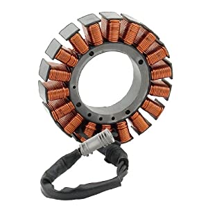
Ok so building the core and such sounds like headache. So has anyone tried using a 3 phase motorcycle stator as our core?

51VgABc1qlL._SL500_AA300_.jpg
 
I have a motorcycle alternator here that I wanted to rewind, fit with neo magnets and turn into a motor, but when I took the epoxy coating off I found the laminations were really thick, around 0.8mm, so the losses would have been way too high for a motor.

Machining the bearing support, can etc is pretty straightforward, I think the sticking point is finding a source of high quality laminations. I believe the power croco people get them laser cut, but suspect that the cost is quite high.
 
magudaman said:
Make the core out of billet to make it easier for machining
The only way this could work is by using a Soft Magnetic Composite blank. Performance would be lower than that of a proper laminated construction for other than very high flux frequencies - pretty vulnerable to breakage, too...

Ref: http://www.endless-sphere.com/forums/viewtopic.php?f=30&t=38624&p=563618
 
magudaman said:
Ok so building the core and such sounds like headache. So has anyone tried using a 3 phase motorcycle stator as our core?

51VgABc1qlL._SL500_AA300_.jpg
Yup lol the Lams are thick and cause heat at hi rpms. You can get ~6000 rpm max with a motorcycle stator. I was aiming for ~12-13000 rpm so it did not work for me, now IM workign with iron powder (SMC) stators. Here see this thread http://endless-sphere.com/forums/viewtopic.php?f=2&t=28748
You will find with a motorcycle stator they are wound different then you will proly want them. Its going to depend on the number of magnets.
 
What you want already exists, and is readily available. If 2kw is really enough, just take the motor out one of the larger geared hubbies like those Cellman sells or a Bafang BPM, and do your own housing that allows for some ventilation and far better cooling than sealed up in a hub. Get the lowest turn count motor they offer for best current handling. If you're interested in more power then the 2 speed high efficiency hubbies I've been testing may be up your alley.

John
 
magudaman said:
Ok so building the core and such sounds like headache. So has anyone tried using a 3 phase motorcycle stator as our core?

51VgABc1qlL._SL500_AA300_.jpg

This is the perfect picture of a bad stator ! Look at how much extra room there is left for more copper ! Thicker wires
would have given the same motor properties but with lower resistance, so with lower losses.
 
On the other hand, thinner wires keep the intense parts of the EM fields close to the ferromagnetic core. Maximum copper fill is probably only the best choice when you'll be pushing a motor to its limits. Folks here do that a lot, but designers of other electric powered gizmos may not have it as a design goal.

Chalo
 
You're right, Miles, it doesn't make any difference. These motorcycle alternators are built right down to a price, with thick (cheap) laminations, poor copper fill (so they can machine wind the stator) and ceramic magnets (again because they're cheap).
 
Jeremy Harris said:
You're right, Miles, it doesn't make any difference. These motorcycle alternators are built right down to a price, with thick (cheap) laminations, poor copper fill (so they can machine wind the stator) and ceramic magnets (again because they're cheap).

It does make a difference. It is just so negligible it shouldn't be taken into consideration.
 
flathill said:
Jeremy Harris said:
You're right, Miles, it doesn't make any difference. These motorcycle alternators are built right down to a price, with thick (cheap) laminations, poor copper fill (so they can machine wind the stator) and ceramic magnets (again because they're cheap).

It does make a difference. It is just so negligible it shouldn't be taken into consideration.

Yes, sorry, I just forgot to put the <pedant> tags around the "any difference" part...................... :wink:
 
Jeremy Harris said:
flathill said:
Jeremy Harris said:
You're right, Miles, it doesn't make any difference. These motorcycle alternators are built right down to a price, with thick (cheap) laminations, poor copper fill (so they can machine wind the stator) and ceramic magnets (again because they're cheap).

It does make a difference. It is just so negligible it shouldn't be taken into consideration.

Yes, sorry, I just forgot to put the <pedant> tags around the "any difference" part...................... :wink:

At least I'm not a pedantic grammar nazi :D

"There are 2 methods used in Magnetics Designer to compute
the fields in the winding stack. The first approach computes the
magnetic fields based on an estimation similar to the
conventional approach described by Dauhajre [24] which
constructs the field from the core outward for solenoid windings
and sideways across the length of the bobbin for sector wound
configurations. The former approach gives good results for a
single sector; however, the latter approach is in error for thin
side-by-side sectors. Fields in the winding stack are influenced
by neighboring currents, causing the field to be centered about
the sector. The algorithms used in Magnetics Designer account
for the sector shapes in distributing the fields. The method for
automatic design uses this method because it is fast enough to
direct the program to a good optimization.

The second method uses the same equations to predict AC
losses, but it makes a magnetic field estimate using the following
equation:
4 r3
dH idl r
π
×
= 4.8.2
An iterative solution is required because the current distribution
in the wires affects the field in nearby conductors. The red lines
in the field map represent the current on the high field intensity
side of the conductor, the field intensity is given by the gray
scale, where black is strong, white is weak. The solution is
basically a quasi-static solution of Maxwell’s equations. The
winding stack magnetic field can be estimated without solving
for the fields within the core by assuming that the core shields
most of the field that penetrate the core. Including the phantom
surface current winding accounts for the gap fringe fields. This
solution is too lengthy to be used for optimization

This site is super fun:
http://www.falstad.com/vector3dm/

Darn flux distortion :wink:
 
why not go for broke, and make a csiro motor?
I think they are good for 8kw or so, windings are a bit different but not too complex.
Not sure if anyone has beaten their efficiency yet ( near 98% peak effic.)
The hallback array would be quite a challenge to do.
 
whatever said:
why not go for broke, and make a csiro motor?
I think they are good for 8kw or so, windings are a bit different but not too complex.
Not sure if anyone has beaten their efficiency yet ( near 98% peak effic.)
The hallback array would be quite a challenge to do.

When did the Csiro become more than a 1kw extreme efficiency hubmotor?
 
i'm referring to the csiro motor first used by nsw uni solar race team, the solar race car motor.
 
Back
Top