EB312 connections

rolf_w

100 W
Joined
Aug 4, 2009
Messages
140
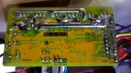
I started to compile infos about the EB312 (AS-2) controller, which I intend to use in my new e-bike built. There are many info-rich threads here on ES, however, I still need to ask all those who know more about this controller to help me filling in the gaps. I would like to know all possible input / output signals of this pcb and their relation to the new XPD release. Following a photo of the pcsb's backside, a sketch of the pads/labels including a list of the connectors which are currently mounted:
eb312_pcb.jpg

EB312_sketch.jpg

Here a list of all connections explaining their intended use. It will hopefully be expanded/corrected and the question marks will disappear:

Abbreviations:
BK ? break signal
CR cruise mode signal (connect to GND to activate)
DX ?
EBS+ ?
EBS- electric brake signal (connect to GND to activate)
GND 1-8 ground (multiple pads)
HE hall sensor signal (replacing speedo pick-up for CA (fit QSA/RSA1 !))
LED ?
P1 LED indicator 1 (connect to common GND or VCC) (... does it indicate speed1 ?)
P2 LED indicator 2 (connect to common GND or VCC) (... does it indicate speed2 ?)
P3 LED indicator 3 (connect to common GND or VCC) (... does it indicate CR mode?)
P4 ?
RXD receive data
SA hall sensor signal A (sensor detecting rotor position phase A)
SB hall sensor signal B (sensor detecting rotor position phase B)
SC hall sensor signal C (sensor detecting rotor position phase C)
SL speed limit signal (connect to ground to force overall speed limit to which all other speed limits (X1, X2) are referenced)
SLA ? ; connected via diode (IN4001) to X3 to CA throttle over-ride
SLK1 ?
SLK2 ?
SP throttle set value (0-5V)
TA pedelec sensor A (hall sensor detecting pedal rotation)
TB anti theft mode (connect to GND to activate / lock the motor)
TXD transmit data
VCC-L controller pos. power supply (interrupt to switch controller off)
XC
XC-
X1 connect or toggle to GND to limit speed1 or cycle speed 1-2-3(-4)
X2 connect to GND to limit speed3
X3
X3-, DX3 reverse mode (connect to GND to reverse rotation and limit speed)
X4 ?
+5V 1-5 5V supply (multiple pads)
 
For experimental reasons I intend to feed the throttle signal either directly or via the CA to the EB312. With the available harness I can:

direct feed: the throttle signal is connected to SP
indirect feed: the CA throttle override signal (Th) is connected to X3 which internally connects via a diode to SLA. I don't know the exact relation between SP and SLA but on the pcb they seem to be connected by a resistor / RC filter - thus X3 will override/limit SP. Both throttle signals can be connected simultaneously whereas the CA signal can only limit the throttle signal.

If I provide an external change over switch to keep the two throttle signals independant I will not need the X3 - I will only connect to SP
If I only use the CA Th signal I'll avoid the change over switch and will only connect to SP

I assume that the rules for the speed limiting modes (SL, X1, X2) are valid for the directly and indirectly fed throttle signal - they are indistinguishable for the uP

are my thoughts correct?
 
Thanks heaps for sharing!
This has filled in a lot of blanks with a new unknown controller i have been playing with
 
rolf_w said:
For experimental reasons I intend to feed the throttle signal either directly or via the CA to the EB312. With the available harness I can:

direct feed: the throttle signal is connected to SP
indirect feed: the CA throttle override signal (Th) is connected to X3 which internally connects via a diode to SLA. I don't know the exact relation between SP and SLA but on the pcb they seem to be connected by a resistor / RC filter - thus X3 will override/limit SP. Both throttle signals can be connected simultaneously whereas the CA signal can only limit the throttle signal.
Your controller has the old style V2-compatible CA-DP interface using a diode. The newer 'Large Screen' compatible controllers use a 1K resistor instead which allows use with either V2 or V3 models. Check out the schematic snippets in "Appendix C. Summary of CA-DP Wiring for Controllers with Old/New Interface Types" of the [strike]Un[/strike]official Guide. The pad labeling there is for the Grinfineon controller but I believe SL1 is the same as your SLA. Anyhow, you can snoop the traces and parts values on your PCB and see if existing parts values will let you just swap the diode for a resistor to upgrade your particular board.

Also, I would tie the white CA Shunt- lead to the shunt pad instead of way over on the main ground bus at Gnd8.

Anyhow, it will be nice to have this all documented in one place - good idea.
 
teklektik said:
rolf_w said:
For experimental reasons I intend to feed the throttle signal either directly or via the CA to the EB312. With the available harness I can:

direct feed: the throttle signal is connected to SP
indirect feed: the CA throttle override signal (Th) is connected to X3 which internally connects via a diode to SLA. I don't know the exact relation between SP and SLA but on the pcb they seem to be connected by a resistor / RC filter - thus X3 will override/limit SP. Both throttle signals can be connected simultaneously whereas the CA signal can only limit the throttle signal.
Your controller has the old style V2-compatible CA-DP interface using a diode. The newer 'Large Screen' compatible controllers use a 1K resistor instead which allows use with either V2 or V3 models. Check out the schematic snippets in "Appendix C. Summary of CA-DP Wiring for Controllers with Old/New Interface Types" of the [strike]Un[/strike]official Guide. The pad labeling there is for the Grinfineon controller but I believe SL1 is the same as your SLA. Anyhow, you can snoop the traces and parts values on your PCB and see if existing parts values will let you just swap the diode for a resistor to upgrade your particular board.

Also, I would tie the white CA Shunt- lead to the shunt pad instead of way over on the main ground bus at Gnd8.

Anyhow, it will be nice to have this all documented in one place - good idea.

Sounds like you know what going on :)
Hoping you might take a peak at this ??? controller and be able to point me in right direction
It came to me without any display/wiring...
Seems like the only connections leaving the box apart from motor/hall/+5v/battery + and - were "TX - RX".... no brake or throttle connections soldered to board???
This post got me closer to getting my ??? controller going... VK+ on ming seems to power up everthing on board. 5v rails etc.
I then tried throttle to SP5v+ , SP and ground... gets me a 0.8-4 volt throttle signal at the SP pin... but controller not trying to turn motor yet.
Any other ideas?
 

Attachments

  • Board.jpg
    Board.jpg
    164.4 KB · Views: 2,204
Well - I know a little about the CA, but don't really spend any time mucking about inside these controllers. I have several of these here - but I never had the need to pull them apart to identify the connection-to-pad correspondence.

I'm a little confused - it looked like you had this pretty much laid out. Are you saying that some of that was supposition and you are looking for verification of the connections you called out?

If that's the case, then you might go back to your first post, press 'EDIT' and change the title to "Need Help with EB312 connections!" and then pose some specific questions about where you are having trouble or are uncertain. I know there are members out there who can help if you can clarify where you need it.

Hope you get this sorted.
 
Sorry inappropriate to hijack rolf's thread mine was posted here originally.
https://endless-sphere.com/forums/viewtopic.php?f=35&t=81133

No idea of correct pinout... i'm just trying to make an educated guess based on what i can measure with multimeter and PCB markings that meant nothing to me.

These 'EB' series controllers were the first thing that i have found that use similar MCU and PCB markings.
 
teklektik said:
D'oh! - I didn't notice the different name - that clears things up a bit.... :oops:

My fault, i should have explained better and i changed the name of my thread to suit better after seeing your post
 
Back
Top