Driving motors, more amps or more volts?

Joined
Oct 28, 2008
Messages
14,539
Location
Manhattan Beach, CA, USA
moderator edit: this thread was split-off from an evolving discussion in the Emrax motor thread, found here:

https://endless-sphere.com/forums/viewtopic.php?f=30&t=88884

xxxxxxxxxxxxxxxxxxxxxxxxxxxxxxxxxx

methods said:
You know I love porn Doc... Good job... But the blog was down.

Magnets:. Glue alone is not acceptable to me. It will age and fail... Or quality in Production will create great risk for failure. Good Production pieces can not fail (Mill Spec).

As for the tiring arguments around making power with Volts and not Amps...
Volts

Yes there is the copper weight issues with big current.
Yes there is the I^2*R issue at every connector and bolt
More importantly is wear and tear on Batteries.

When taking Luke advice it is important to know what he is up to. Luke is an extreme guy... He wants extreme things... Like... A 20Ah battery that can discharge at 2000A.

That's cool... Plenty of need for that... But I see a different need in our sector.

Low cost
High cycle count
Light weight

If I can string cells in series and pull 1C off of them instead of 10C with bursting of 30C... This treats the chemistry better and will result in longer life. I would like my cells to cycle thousands of times... And I have never seen cells last that many cycles while discharging at super high rates.

Not here to argue.
Let's just see what the lifecycle ends up being on Luke's 28S packs. They get pushed pretty hard... Upward of thermal limits. My guess is they will show premature wear.

It is nice to be able to charge fast. That is of super high value.

I can say this:. As lithium batteries get used and abused their internal resistance goes up over time. IF you depend on that IR being low then performance will degrade with time... As users bump against thermal limits.

On the other hand... If you make power with voltage and draw only 1C off your cells... The internal resistance can go up and it will have much less effect (exponentially less).

Drag racing and Motorcycles are one slice of a very big pie. They have strict boundaries and clear goals. These limitations and goals do not nessesary align with the limits and goals of other platforms.

Then there is simple scaling.

420V 1000A Tesla
Do you think you will see 105V 4000A Tesla
No
You won't
Ever

Ohm's law.
To break it is to fail to scale.

-methods


I didn't realize I had a spokesman who preaches confusion in my name for me.

If you want to have say 100kW, and you have say 100 cells to make the math easy, if you put all 100 cells in parallel, and you draw 100kW, you are loading each cell at 1kW, it has the voltage sag of a 1kW load and it makes the heat of being loaded at 1kW per cell. If you arrange the same 100cells into a series string and draw the same 100kW from it, each cell is loaded at the same 1kW per cell, each cell has the same voltage sag, each cell makes the heating of 1kW discharge per cell etc.

What changes is the cross section needed in the power busing. If you are able to locate your battery at your inverter, and your inverter at your motor, then your bussing mass can approach zero, no matter the cross section required.

Current is not the enemy of EVs, it just requires doing real interconnections correctly. Voltage and its capacitively coupled efields and corrosion potential and corona and dielectric breakdown from humidity and/or UV exposure are in my own limited set of life experiences, much greater issues to overcome than getting high current interconnects right.

That said, I respect your own thoughts on it and you're welcome to believe/preach anything you like.
 
Depending on the flexibility in pack geometry, it doesn't actually have to be a practical increase in bussing mass or interconnect heating.

If you imagine taking the same series string, cutting it and rotating them all 90deg, you can have approximately identical current density and interconnect heating for a given mass of interconnect conductor mass. Only the end terminations require additional mass, and packaged well with good geometry works out fine.
 
liveforphysics said:
Depending on the flexibility in pack geometry, it doesn't actually have to be a practical increase in bussing mass or interconnect heating.

If you imagine taking the same series string, cutting it and rotating them all 90deg, you can have approximately identical current density and interconnect heating for a given mass of interconnect conductor mass. Only the end terminations require additional mass, and packaged well with good geometry works out fine.

Thinking of the tesla example, none of the cell level connectivity should require additional mass, however the stranded conductors that connect pack to the inverter/drive unit would require some additional capacity. We're talking about negligible amounts compared to the total system mass however.
 
Ohbse said:
liveforphysics said:
Depending on the flexibility in pack geometry, it doesn't actually have to be a practical increase in bussing mass or interconnect heating.

If you imagine taking the same series string, cutting it and rotating them all 90deg, you can have approximately identical current density and interconnect heating for a given mass of interconnect conductor mass. Only the end terminations require additional mass, and packaged well with good geometry works out fine.

Thinking of the tesla example, none of the cell level connectivity should require additional mass, however the stranded conductors that connect pack to the inverter/drive unit would require some additional capacity. We're talking about negligible amounts compared to the total system mass however.


Yep, hence saying approximately identical. You do have some conductor penalty in bussing mass. It's just a tremendous bargain to trade a couple pounds of extruded aluminum or whatever in exchange for the priceless life safety reduction in design drama through simplicity.

But many ways to solve the puzzle work out fine. Even if you never want to deal with over say 800amps of phase current, there are no rules on how many phases you make. Run 24 isolated phase windings or whatever it takes to make current sharing easy, and locate the controller at the motor, and the battery at the controller and it doesn't matter how many phase leads you have, done right the phase leads are located on the PCB right above the mosfet phase lead joint.

Systems can be as clean and simple and safe as you design then to be. A lot of what is done today is based on legacy motor inverter drives for factories where equipment is located hundreds or thousands of feet apart from the power drop. When you can locate the equipment with your own packaging, you can do better.
 
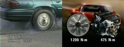
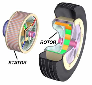
Back in 1994 when Hydro Quebec developped their hub motor car wheel ( called: Moteur Couture)and showed us insane torque on an prototype using a old Chrysler intrepid,

What was great is that they had the motor controller installed right inside the hub. Phase lead was like innexistant... A controller direct to the motor!! 8) it was hard work with the existing semiconductor at that time.. as rds ON was very high...

I remember they says that the limiting factor was the battery and the semiconductor.. as well we were in 1994!.. 23 years ago! this show you all that technology improovement allow to make design change and think different( no i'm not a apple fan..)

Hub motor was developped a century ago.. but the next real improovement was done in 1994 by Dr. Pierre Couture in Quebec. The LFP and Polymer electrolyte (called ACEP during that time) battery wes also in big part developped in Quebec in the 1990.

Moteur-roue+fumes.jpg


Mot-roue+Couture+72.jpg


Video of the motor in action.
https://youtu.be/rhqs91DIp1A?t=2m43s

Doc
 
liveforphysics said:
...
I didn't realize I had a spokesman who preaches confusion in my name for me.
...


Your mixed up Luke.

I am preaching (arguing really... as I am not a church man) that they should not listen to you as the end-all... regardless of whether I am right or wrong... because your perspective is over-specialized.

The squaring effects of current in the nodal parts of the system go exponential with high current and you are proposing that you can avoid this somehow through compaction of a mechanical system.
Noise and issues with high voltage are of course still a problem to solve.

One is a mechanical problem that converges on infinity and does not scale to reality (distributed systems)
The other (high voltage) is a matter of engineering which has been proven to be solvable.

I am arguing for a solvable problem and you are arguing that you can jump the gap of infinity.

Dont care, not looking back on this thread.

-methods
 
Ohbse said:
Thinking of the tesla example, none of the cell level connectivity should require additional mass, however the stranded conductors that connect pack to the inverter/drive unit would require some additional capacity. We're talking about negligible amounts compared to the total system mass however.

If I want to increase a distributed system output by 20% I can simply add another few modules in series and increase my mechanical envelope (which you cant do on a Motorcycle) to bump the voltage from 320V to 380V to 420V... use the same cables, same interconnects, same contactors, yes add a few slaves...

Or - I have to draw harder on my cells... or change the entire system to different cells or paralleled cells.
Thats the part that does not scale and speaks to cell wear.

Its an argument of scalable system.
The motorcycle paradim is not the end-all. We have more problems to solve which are larger and more distributed and involve a lot of logistics that are hand waved away with fantasy arguments about components which can accept current increases of double or triple. Many components can handle a doubling of voltage. Few can handle a doubling of current without total redesign.

EDIT: I have seen systems (Azure) which achieved increased output by stacking systems in parallel. All components had to be duplicated including interconnects, contactors, and slaves. Changes could only be made in 2X. Tesla's system can be incremented in 60V steps for finer resolution with less duplication of components. More of a Systems approach, Production approach, qualification approach has to be used in the analysis as opposed to what hypothetically could be. When I see a motor that can run 4000A the same as 1000A I will rest my case. I do see many controllers that can run 200V as well as 400V.


-methods
 
Final Argument:

Lets see how the Zero Motorcycle design scales with time.
The only way they can get incremental increases in power output is through higher quality cells.

28S 4P is the design... where do you go with that next?
It is completely dependent on cell development.

I am looking at it from a Systems perspective, Qualification perspective, Production perspective, tooling up, qualifying, integrating, managing cost.
If we want incremental increases without total redesign then stacking smaller packs in series makes more sense.

I am looking at the Zero next to the Lightning in the performance variability department.... and my interest is really in platforms which are not limited by mechanical space... are distributed... and want to avoid total redesign where possible.

Of course - a Monolithic BMS does not scale in the voltage domain... and of course BMS's are what I think about constantly.

Why am I still here?
Leaving :D

-methods
 
methods said:
Final Argument:

Lets see how the Zero Motorcycle design scales with time.
The only way they can get incremental increases in power output is through higher quality cells.

28S 4P is the design... where do you go with that next?

If that's the final argument than you're going to be happy to learn it's a non-concern.

Even on the old 2013 Zero cell tech, single module (1p 28s) dirt bikes make 28hp on the dyno. So, on bikes with 4 cells in parallel (S/DS) etc, the pack bussed and ready for >100hp.

Zeros performance increaseing path as the battery sits today enables a full doubling of today's output power performance. With no other battery improvements. Running dual Size6 controllers gets that job done nicely. If they wanted more power than that, putting all the cells in a big series string would not buy even 1 more HP or add any increased power potential to the battery (that wouldn't happen unless you increased the number of cells in the pack).

Perhaps some confusion left around "current nodes" and what you're claiming gives you some squared loss drama. I'm not arguing a bit that I^2*r equals power loss as heating in a circuit. Sizing the conduction path correctly with geometry to keep current density staying uniform through the material, you increase conductor bus cross section as needed.

The most reliable and rugged tech in any EV is it's conductor cross sectional area. To date, I've yet to see properly selected wire or busing cross section wear out, shrink or fail. In my humble experience this makes it the most reliable part of EV design to embrace getting right and enjoy the advantages.


methods said:
Why am I still here?
Leaving :D

-methods

For the same reason I'm here, to learn and share and evolve our personal misconceptions to better fit into whatever the true nature of reality may be.
 
Arlo did a dual controller Zero. 81 hp. I think he even had a thread where he posted details about it, but I couldn't find back to it.

[youtube]3eL0EMFPnVw[/youtube]
 
Having implemented V2 of the Production Qualification tester that qualifies Lukes packs... lets look at the actual math of what they can do:
(Circa 2013/2014)

(btw Sorry Doc... we will get back on topic...)

28S 1P pack (cell box) running 60A continuous with 240A bursts causes significant heating.
Since we were all around in the Car Audio days... we know that we rate things on Continuous Power, not Peak Power.

28*3.7*60 = about 6KW
6KW * 4 = about 24KW

So unless your cell box can put out more than 6KW continuous before overheat your actually talking about a 25hp bike.

Sure it can burst 24Kw * 4 = 100KW... BUT THAT IS BURST/PEAK POWER.... not to be confused with what we could consider RMS power (in Car Audio terms)
(Since we are in Doc's thread)

So... just a reminder to everyone... Dyno numbers are irrelevant unless they show an endurance test or the purpose is to drag race.
Yes I understand that in a MOTORCYCLE application the peak power power needs vs integral of power needs... result in an "experience" closer to the peak performance... so to a rider of a Zero it might as well be an 80hp bike... so well done.

BUT... More to my real irritation...
Zero has been saying for years that they would help cover the Power Systems in alternative markets... and the reality there.. . is a steady state draw with almost no cooling... in many cases.

I learned from Luke that Thermal is one of the greatest degradation factor in cells... and running them to 100hp will cause significant heat... which will shorten life.... so I need to rate the cell boxes at 60A continuous or less... so 6hp

But that is of no consequence.

I am going to try to quit picking at Luke. We are looking at going with a competitors system and it is becoming a conflict of interest for me to speak of his design.

As for the Cell Manufacturer... I am a fan of Farasis. They offer the cells in many different shapes and forms.

As to Lukes commend that stringing the cells in series wont make more power than running them in parallel... that statement can be both true and false. Of course with the naive analysis it is true. Given a bigger picture systems approach it becomes less and less true. Putting Constants into the equation exposes this.. like fixed KV at the motor. As a systems guy my view is much different since I am often forced to take a set of 6 or 7 constants, play with only 3 variables, and come out with a good result.

Luke thinks one-off... so he always argues with 10 variables... which just is not my reality.
So - no need to argue.

thanks,
-methods
 
Nice answer buddy.

In practice, it took 6 full race/charge sessions at Laguna Seca of riding on the track as hard as I could, followed by 1C fast charging in the sun all day to reach 52degC on my DSRs monolith battery. During the ride back home from Laguna the 52degC pack went down to 48degC.

I know Jamie was able to reach first stage battery temp cut back level just before his last session at the end of the day, but he is a far better rider than myself and able to hold a significantly higher average discharge power while road racing all day.
 
methods said:
Luke thinks one-off... so he always argues with 10 variables... which just is not my reality.
So - no need to argue.

thanks,
-methods

I'm flattered, but I've been sadly lacking in 1-off style designs for the last 3-4years. Everything that gets my design energy today is optimized around longest service life in the field, design for manufacturability and safety in manufacturing, along with unmatched vibration and weather resistance. I spend 10x-50x more time in vibration tables, environmental chambers, and salt fog spray chambers than I do playing with anything 1 off these days.

But again, you're always welcome to believe whatever you like my friend.
 
Macribs. I have helped on an even more powerfull dual controller project with 2 size 6s. Hope the builder will share it soon ;)

I just want to go fast.

HV sucks but we will need some voltage for things...

I think commuter motorcycles and moderate perforamance MC stuff will be fine with ~100v But jumping to ~360v or even more makes the controller size about 4x smaller...

There is a limit in the controller department and its how much current the IGBTs or FETs can flow Take a TO264 or TO247 package its limited to its legs at 160 amps. So if you use it at 160 amps with 100v vs 160 amps at 360v which one will make more power.....

Sure running dual controllers is super cool but a controller of just about the same size (HV caps are bigger) with 2x the voltage you can have the same power of dual controllers with just 1. I want to work hard to keep the voltage as low as possible but we need some to make the power....
 
Dual size 6 controllers. Also for a Zero Mc? Wow I bet the thing will just fly off the line.

For e-bike and e-motorcycles the biggest issue is that real estate is premium. Creating hi voltage packs might be hard to do in regard to whatever real estate is available. I mean the higher motor RPM is nice, but lowering Ah to get more cells in series would mean shorter lasting rides?

Lets use Zero as an example. I will use 18650's as those cells make sense in regards to size that I am familiar with. Replacing a dead stock battery I am for this example using 18650 cells, 1000 cells should be an easy number for the math? 20s 50p? If samsung Q30 was chosen the 50 kilo battery pack would be 72v 150 Ah. 10 650 Wh. Max battery current 700 A. Agree?

Now if we double the voltage and make a 40s 25p pack we now have 144 v 75 Ah. 10 650 Wh. And 350 A. Or we could go for 300 v pack.
For ease lets say 80 s 13 p. We now have close to 300 v but we also have half the Wh and half the A.

How would these higer voltage packs change the behavior of the motorcycle? I get it we only got one controller to worry about. But what about range? And how will repeated WOT from stand still be affected compared to the first pack the 20s 50 p?

W = A x V
so we got the same power output from the motor in all cases. But as the voltage increases the max RPM rises too giving more high speed and that let us use different gearing. We should with the 300v pack be able to match the acceleration of the first example pack. But what about maximum distance on 1 fully charged pack? Would the max riding distance change when voltage increases?

What parameteres could make problems? Eddy current? And will there be any gains if hi voltage is chosen, like less resistance in wires or pack?
 
You would be winding the motor for the proper voltage.

I am talking from a clean sheet of paper for all comparisons.


If you use 1000 cells in any configuration you always have the same WH and W available.

But if you design a controller to make the same power at 2x the voltage its 1/2 the size
 
macribs said:
For e-bike and e-motorcycles the biggest issue is that real estate is premium. Creating hi voltage packs might be hard to do in regard to whatever real estate is available. I mean the higher motor RPM is nice, but lowering Ah to get more cells in series would mean shorter lasting rides?

It's all in the motor winding, which determines how many revolutions you make per volt, and adjusts how many amps you need to make X amount of torque or RPM. A high voltage and low voltage setup can be exactly the same size in battery and motor.

I like some high amp, low voltage motors. I've done 45mph continuous on the flats on a 47V bike with amazing front wheel flipping torque.. it just requires 8 gauge battery cables AT A MINIMUM, huge connectors, and a lot of cells in parallel instead of in series..

Or.. on the opposite end, you can do 12 gauge wires, 200v and 20 amps to make the same power, with a super slow winding motor. Although balance charging a 52 series battery is going to be a problem of it's own..

I like big power buses and low counts of cells in series because it makes manual balancing with RC chargers a lot easier. 10S is my favorite. But you can adjust your powertrain design to taste though, using the number of turns in the motor as the starting point of the design.

Anyway, we should be talking about an emrax 228 here, shouldn't se.. :mrgreen:
 
Arlo1 said:
if you design a controller to make the same power at 2x the voltage its 1/2 the size

Usually, right? i mean, some FETs like lower voltage and can handle higher amps.. FETs that can handle really high voltages usually handle very little amps..
3077 FET... 3mOhms.. 4115 FET.. 10mOhms.. around triple the voltage handling, around triple the resistance.. go figure.

My quick 47V bike does use an 18FET when i could probably get away with a 12FET at higher voltage.. but the controllers do not scale in size along with their FETs. I used a 12FET with 3077's for a while, but the battery input stage of the power bus would get too hot. With a redesign of the board ( no thanks, not doing that ), i could get away with a 12FET just the same.
 
neptronix said:
Arlo1 said:
if you design a controller to make the same power at 2x the voltage its 1/2 the size

Usually, right? i mean, some FETs like lower voltage and can handle higher amps.. FETs that can handle really high voltages usually handle very little amps..
3077 FET... 3mOhms.. 4115 FET.. 10mOhms.. around triple the voltage handling, around triple the resistance.. go figure.

My quick 47V bike does use an 18FET when i could probably get away with a 12FET at higher voltage.. but the controllers do not scale in size along with their FETs. I used a 12FET with 3077's for a while, but the battery input stage of the power bus would get too hot. With a redesign of the board ( no thanks, not doing that ), i could get away with a 12FET just the same.
Once you replace the high voltage fet with an IGBT you are back to the same current limits.
Most good FETs and IGBTs will run at an RMS of the package/leg limits. So voltage doesn't effect the current limit.
 
Back
Top