Modify controller to handle more volt

Pota

100 W
Joined
May 15, 2017
Messages
147
Hello all,

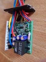
Ive bought 2 Controllers (48v 30amp)

Ive modded the shunt, but i have problems adding more volt than 48v to one of them.

They are pretty much the same. They are made for cheap Electric scooters. Like Evo scooter.

One of them can be overvolt as much as i want, but the other only accept 6v extra (max 54v).
Whats is limiting it to only 54v? Are there any mod i can do to make it handle more than 54v like the other Controller?

Thanks for all replies

Pota
 
Somewhere on the board there is a pair of small resistors that will set the cutoff voltage. It may be hard to find the right ones without doing some poking around with a voltmeter. It might be obvious. If you post a good picture of the board, we might be able to spot it.

Plan "B" is to take the key line and lower the voltage on that. Most controllers will have a fat red wire that goes to the battery and a skinny one that also goes to the battery, but can run through a key switch if you want on/off function. The skinny red wire doesn't take a lot of current, so you can place something in series with it to lower the voltage or feed it from a fixed voltage regulator. Then you can put any voltage on the fat red wire and it will go.

Be sure to pay attention to the voltage ratings on the main capacitors and the FETs. It is pretty easy to blow things up. Most 48v controllers can handle a maximum of about 60V.
 
fechter said:
Somewhere on the board there is a pair of small resistors that will set the cutoff voltage. It may be hard to find the right ones without doing some poking around with a voltmeter. It might be obvious. If you post a good picture of the board, we might be able to spot it.

Plan "B" is to take the key line and lower the voltage on that. Most controllers will have a fat red wire that goes to the battery and a skinny one that also goes to the battery, but can run through a key switch if you want on/off function. The skinny red wire doesn't take a lot of current, so you can place something in series with it to lower the voltage or feed it from a fixed voltage regulator. Then you can put any voltage on the fat red wire and it will go.

Be sure to pay attention to the voltage ratings on the main capacitors and the FETs. It is pretty easy to blow things up. Most 48v controllers can handle a maximum of about 60V.

Thanks for all the good info :)

Ive added some picture of it. What could be done?
 

Attachments

  • 20171003_173615.jpg
    20171003_173615.jpg
    249.8 KB · Views: 1,561
  • 20171003_173631.jpg
    20171003_173631.jpg
    328.9 KB · Views: 1,561
  • 20171003_173648.jpg
    20171003_173648.jpg
    203.5 KB · Views: 1,561
fechter said:
Somewhere on the board there is a pair of small resistors that will set the cutoff voltage. It may be hard to find the right ones without doing some poking around with a voltmeter. It might be obvious. If you post a good picture of the board, we might be able to spot it.

Plan "B" is to take the key line and lower the voltage on that. Most controllers will have a fat red wire that goes to the battery and a skinny one that also goes to the battery, but can run through a key switch if you want on/off function. The skinny red wire doesn't take a lot of current, so you can place something in series with it to lower the voltage or feed it from a fixed voltage regulator. Then you can put any voltage on the fat red wire and it will go.

Be sure to pay attention to the voltage ratings on the main capacitors and the FETs. It is pretty easy to blow things up. Most 48v controllers can handle a maximum of about 60V.

Can you spot it? And if you do, what should i do with it?
 
Post pictures of the controller that works at the higher voltage. Then separately post pics of the lower voltage one. Try to use the same camera angles for both sets of pictures. I'm not sure what I'm looking at in those 4 pictures. These controllers are for brushed motors. Do they have the same mosfets in them? What voltage have you used on the one that allows higher voltage? What mosfet is in these controllers? It looks like the caps are 62 volts so it's hazardous at best to exceed that voltage and the caps won't last long running at 62 volts. There's really good reasons why 54 volts max is used on this controller! If you want higher voltage as a rock bottom minimum you want to replace all the 62 volt caps with 100 volt versions of the same values. The mosfets are very likely to be rated for 60 volts so they will need to be replaced as well for 100v mosfets such as IRF4110 or AOT290's. Frankly, run these things at 54 volts max and if you need more voltage, just get higher voltage motor controllers. By the time you go to the effort of upgrading them for more voltage, you will have paid for better controllers anyway.

Looking at the pictures I see 7805 and 7815 linear voltage regulators. I see none of the components needed for a proper DC-DC converter. It's needed to step down batt voltage to something that the MCU would use. most of these small linear regulators are not going to run for long at more than say 48 volts. Essentially everything I see about these controllers tells me to NOT bother upgrading them in any way and to NOT run them hotter than 48 volts. You will quickly blow them up.

If you need more voltage for a brushed controller, this one ought to work for you.

http://www.ebay.com/itm/12V-24V-60V-72V-30A-PWM-DC-Motor-Speed-Control-Controller-Dimmer-7V-80V-30A-/161063406364?hash=item2580208b1c:g:c3UAAOSwa~BYa4iz
 
Just buy another more powerful controller those things are a dime a dozen at that power level. Lots of people looking to ditch their old lyons, maybe some for cheap.
 
flat tire said:
Just buy another more powerful controller those things are a dime a dozen at that power level. Lots of people looking to ditch their old lyons, maybe some for cheap.

It's a brushed controller, not brushless, but yeah...that's what I said too.
 
Yes, that type of controller is very inexpensive. Might be better to just get a new one.

I've reverse engineered a YK42, which is very similar. There is no circuitry that will disable for over voltage, only under voltage. Somehow I think your problem is not being caused by an intended protection circuit. It may be an "unintended" protection circuit.

About the only thing I would suggest trying is to place another resistor in series with the big 1.2K that feeds the voltage regulator. If it cuts off at 54 but you want 60v, then maybe add 220 ohms in series with it and see if that works.

Brushed controller 1.jpg
 
fechter said:
Yes, that type of controller is very inexpensive. Might be better to just get a new one.

I've reverse engineered a YK42, which is very similar. There is no circuitry that will disable for over voltage, only under voltage. Somehow I think your problem is not being caused by an intended protection circuit. It may be an "unintended" protection circuit.

About the only thing I would suggest trying is to place another resistor in series with the big 1.2K that feeds the voltage regulator. If it cuts off at 54 but you want 60v, then maybe add 220 ohms in series with it and see if that works.


When you talk about connecting one i series, you mean connect one more of them?

Whats strange is that i have a similar controller which allows more than 54v. And i mean same product.
 
Yes, disconnect one end of the existing resistor and place one in series with it.

I don't think this is a normal function for this controller, so not sure why it would do this, but the resistor might fix it.
 
Back
Top