
Jil
1 kW
Hello VESC users !
I need your advices...
I tried to set my VESC controller (Turnigy 50A) and motor (Turnigy SK3 5055) with the VESC tool (new interface).
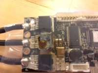
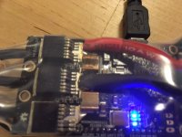
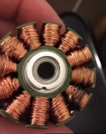
I was using the motor setup wizard on FOC mode. And when I arrived on the FOC settings page, I entered the R value indicated in the motor specifications (31 mOhms, instead of 15 as a standard value on the VESC tool), then I cliced on the "RL" button to start measurment of resistance and inductance values (see image 5 attached)... and my motor burnt in a few seconds ! The motor is dead, but my VESC seems also to be damaged (see photo).
I have set max current values (50A for the battery, which is a Lipo 4S 10Ah 10C, and 20A for the motor), so I just do not understand what happens. Mistake on my side, failure of the VESC ?
I have made some trials before with the VESC tool (using keypad arrows to action the motor) everything was working perfectly...
Do you have an idea of what could have happened ?
Many thanks for your help !
Jil
I need your advices...
I tried to set my VESC controller (Turnigy 50A) and motor (Turnigy SK3 5055) with the VESC tool (new interface).
I was using the motor setup wizard on FOC mode. And when I arrived on the FOC settings page, I entered the R value indicated in the motor specifications (31 mOhms, instead of 15 as a standard value on the VESC tool), then I cliced on the "RL" button to start measurment of resistance and inductance values (see image 5 attached)... and my motor burnt in a few seconds ! The motor is dead, but my VESC seems also to be damaged (see photo).
I have set max current values (50A for the battery, which is a Lipo 4S 10Ah 10C, and 20A for the motor), so I just do not understand what happens. Mistake on my side, failure of the VESC ?
I have made some trials before with the VESC tool (using keypad arrows to action the motor) everything was working perfectly...
Do you have an idea of what could have happened ?
Many thanks for your help !
Jil
")