Number of Poles - for setting speedometer

Joined
Oct 18, 2017
Messages
104
I just got my CA-DP version 2. I am trying to set the number of poles so the speedometer works properly. I have a 1500 watt geared Mac motor hooked up to an infineon 12fet 3077. I have a small magnet and speedo sensor on the CA, so I have it set to 1 pole initially. But anytime I use the throttle the speedo goes crazy (blurred numbers and/or reads off the charts (58/59mph) when going very slow. It is also exaggerating my distance traveled. It is clear I need to set a different number of poles. I have set the wheel circumference properly. If anyone has info let me know. Hoping not to connect to a volt meter but will if that is the only way. Thanks!
 
changeissimple said:
I have a small magnet and speedo sensor on the CA, so I have it set to 1 pole initially. But anytime I use the throttle the speedo goes crazy (blurred numbers and/or reads off the charts (58/59mph) when going very slow.
....
It is clear I need to set a different number of poles.
Not really.

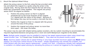
I looks like your config is fine but that you have a switch closure issue with the pickup. Here's the installation notes from the CA3 Guide - same pickup - same requirements and issues.

Try fixing the alignment and gap and see if the problem goes away. If not you probably have a bad sensor.

CA_wheelPickupInstallation.png
 
I have the sensor and magnet set up properly. When I am off the throttle it reads properly, but when power is being delivered to the motor it reads blurred numbers or 59mph. Any help??
 
changeissimple said:
I just got my CA-DP version 2.
Just noticed this is a CA-DP not a CA-DPS so I'm guessing you connected the speed sensor yourself.

How did you connect the speed sensor to the CA?
Is it a regular CA speed sensor from Grin or a bike computer or other sensor?
 
Is it possible you have the separate speed sensor wired in parallel with the motor's hall signal on the DP connector?

If so, you'll get pulses from the motor (which you don't want) mixed with the pulses from the sensor (which you do want), but only when the motor is activated (because it's a geared motor so it's halls aren't triggered except when motor is powered, or if it's rolled backwards).


To test for this, get off the bike and roll it's motor wheel backwards, and watch the speedometer reading. If it gets a reading, then this is what is happening. (assuming the speed sensor is on the non-motor wheel. if the speed sensor is on the mtoor wheel, remove the magnet temporarily)

To fix it, you'll need to disconnect the speed sensor wire from the controller's CA connector (but not the one from the speed sensor to the CA).
 
amberwolf said:
Is it possible you have the separate speed sensor wired in parallel with the motor's hall signal on the DP connector?

If so, you'll get pulses from the motor (which you don't want) mixed with the pulses from the sensor (which you do want), but only when the motor is activated (because it's a geared motor so it's halls aren't triggered except when motor is powered, or if it's rolled backwards).


To test for this, get off the bike and roll it's motor wheel backwards, and watch the speedometer reading. If it gets a reading, then this is what is happening. (assuming the speed sensor is on the non-motor wheel. if the speed sensor is on the mtoor wheel, remove the magnet temporarily)

To fix it, you'll need to disconnect the speed sensor wire from the controller's CA connector (but not the one from the speed sensor to the CA).

To connect the Cycle Analyst I plugged the 6 wire connector attached to the CA into the 6 wire connector on my controller, that is the only plug i had to use. It plugged in directly. No separate wires. It has a speed sensor that I ran down the front fork and properly aligned the magnet and measured circumference. And I just ran your suggested test and if I roll the bike backwards it immediately reads 58/59 mph. So how do I remove the speed sensor from the controller's connector? Is there a way to set the poles to read the speed properly? instead of cutting wires? Thank you for the helping, we are getting closer to a solution! This is a great forum!
 
changeissimple said:
So how do I remove the speed sensor from the controller's connector?
On the CA or the controller side of the connector, you can pull the insulation back (I'd do it on the controller side) and find the yellow Speed wire. It may not be yellow on the controller side so follow teh pinout below
CA3_Pinouts_2017.jpg


I'd cut it at least a couple inches back from the connector in case you ever need to use the controller with a DD hub that *can* be used as the wheel speed sensor (or otherwise need to read the motor sensor speed), so you can splice it back together in that case.

Is there a way to set the poles to read the speed properly? instead of cutting wires?
No, because your external sensor uses just 1 pole.

The internal sensor can only read the motor speed, not the wheel speed, because it's a geared motor. That's why it works normally when not using the motor.

If you change the number of poles from 1 to whatever is needed for the motor, then you'd need to leave the magnet off the external wheel sensor, and then you can only get a speed reading while the motor is in operation and driving the wheel--whenever the motor runs at less than wheel speed, the speed reading will be wrong. If you are just coasting, speed reading will be zero.
 
Back
Top